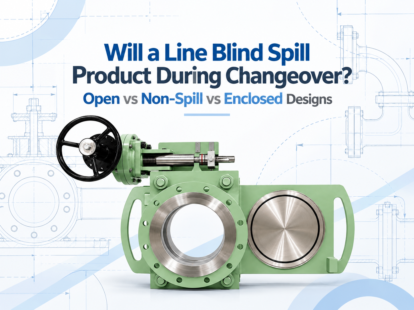
네, 개방형 라인 블라인드(line blind)는 개방 위치와 차단 위치 사이로 전환할 때 잔류 제품을 방출할 수 있습니다. 무유출 설계는 해당 잔류물을 사라지게 하는 것이 아니라, 부분적인 밀폐 공간에서 액체를 포집하여 드레인으로 유도합니다. 밀폐형 설계는 액체와 증기를 더 잘 제어할 수 있지만, 하우징, 드레인, 벤트 및 퍼지 연결부가 해당 용도에 맞게 설계된 경우에만 그렇습니다. 이러한 명칭 중 어느 것도 가압된 상태에서 블라인드를 이동시켜도 된다는 허가로 해석되어서는 안 됩니다. 전환 중에 제품이 유출될 수 있는 이유 라인 블라인드line blind가 완전히 클램핑되면 씰이 공정을 유지하고 솔리드 플레이트가 차단 위치에서 확실한 격리를 제공합니다. 전환 과정은 다릅니다. 스펙터클 플레이트나 슬라이딩 플레이트가 움직이기 전에 씰링면이 분리되어야 합니다. 그 간격 동안 바디 캐비티와 플레이트 통로가 주변 지역에 개방될 수 있습니다. 배관은 이미 차단되고, 압력이 제거되며, 비워져 있어야 하지만, "비워졌다"고 해서 완벽하게 건조하다는 뜻은 거의 아닙니다. 액체는 플레이트 위에 막 형태로 남아 있거나, 하부 본체에 고이거나, 배출이 잘 안 되는 배관 주머니에 고여 있을 수 있습니다. 가스 설비의 경우 인화성, 독성 또는 냄새가 나는 증기가 남을 수 있습니다. 따라서 배출되는 양은 라인 블라인드 그 자체만큼이나 배관 레이아웃과 차단 절차에 따라 좌우됩니다. 세 가지 디자인은 잔여물을 다르게 관리합니다 오픈 바디 디자인 노출된 플레이트 경로에서 잔류 액체가 임시 트레이나 작업 구역으로 떨어질 수 있으며, 증기는 국소적으로 확산됩니다. 이 배치는 용이한 접근과 육안 점검이 중요한 물, 스팀 응축수 또는 기타 관리 가능한 매체에 적합할 수 있습니다. 바닥 오염 및 작업자 노출 가능성이 가장 높습니다. 비유출형 설계 하단 및 측면 커버가 드립을 받아 드레인이나 회수 용기로 보냅니다. 상단은 열려 있을 수 있습니다. 이 설계는 지상 또는 갑판 오염을 제어해야 하는 연료 터미널, 해상 서비스 및 액체 작업에서 일반적으로 고려됩니다. 액체가 떨어지는 것은 줄여주지만 증기를 봉쇄하지는 못할 수 있으며, 드레인이 막히면 그 목적을 달성하지 못합니다. 밀폐형 설계 하우징은 플레이트 이동 경로의 전체 또는 대부분을 감싸며 밀폐형 드레인, 퍼지, 벤트, 플레어 또는 증기 회수 시스템에 연결될 수 있습니다. 이는 제어된 격리가 요구되는 독성, 가연성, 유독성 또는 환경 민감성 용도에 더 적합합니다. 단점은 퍼지, 검사 및 유지보수의 복잡성이 커지고 갇힌 압력을 의도적으로 관리해야 한다는 점입니다. 이러한 명칭은 제조사 간에 완벽하게 표준화되어 있지 않습니다. 한 공급업체의 '무유출(non-spill)' 모델은 상단이 열려 있을 수 있는 반면, 밀폐형으로 설명되는 다른 제품은 더 완전한 케이싱을 사용할 수 있습니다. 견적 요청서(RFQ)는 제품 이름에 의존하기보다는 밀폐 배열을 보여주고 모든 개구부를 식별해야 합니다. 무유출이 자동으로 제로 방출을 의미하는 것은 아닙니다 휘발성이 낮은 액체의 경우, 남은 방울을 받아 밀폐된 용기로 유도하는 것으로 충분할 수 있습니다. 휘발성 탄화수소는 다른 문제를 야기합니다. 액체는 포집될 수 있지만 증기는 열린 상단이나 벤트를 통해 계속 빠져나갈 수 있습니다. 독성 가스 서비스에는 가시적인 액체와 보이지 않는 방출 경로 모두에 대한 제어가 필요합니다. 하우징 또한 올바르게 이해되어야 합니다. 일부 하우징은 압력 정격이 부여된 2차 경계가 아니라 수거 커버입니다. 액체를 담은 상태에서 캐비티가 격리될 수 있는 경우, 태양열 가열이나 공정 온도 변화로 인해 열압이 발생할 수 있습니다. 따라서 설계에는 안전한 벤트 또는 열방출 경로가 필요합니다. 작업자 바로 옆에서 배기하는 것은 노출 위치를 장치 하단에서 상단으로 이동시킬 뿐입니다. 밀폐형 서비스의 경우, 드레인과 벤트가 종단되는 위치를 명시하십시오. 적절한 배출처로는 제품에 따라 밀폐형 드레인, 회수 용기, 스크러버 또는 플레어 시스템이 포함될 수 있습니다. 퍼지 매체, 퍼지 순서, 허용 배압 및 커버를 열기 전에 캐비티가 안전한지 확인하는 방법을 확인하십시오. 전환 절차가 여전히 가장 큰 위험을 제어합니다 라인 블라인드(라인 스페이서)는 일반적으로 상류 및 하류 에너지원이 현장 절차에 따라 격리, 잠금 또는 기타 방식으로 안전 조치된 후에만 교체해야 합니다. 해당 섹션은 압력을 낮추고(감압), 드레인(배수)해야 하며, 필요한 경우 세척 또는 퍼지(가스 치환)해야 합니다. 게이지 연결이 막힐 수 있는 경우 압력 지시계만으로는 충분히 확인할 수 없으며, 승인된 블리드(방출구) 또는 드레인을 통해 직접 확인할 수 있습니다. 클램프를 풀기 전에 작업자는 드레인 경로가 열려 있는지, 수용 시스템에 용량이 충분한지, 블라인드 본체에 갇힌 압력이 없는지 확인해야 합니다. 이동 후에는 라인이 다시 가동되기 전에 플레이트가 완전히 제 위치에 자리 잡고 다시 클램핑되어야 합니다. 무유출 하우징은 완전하지 않은 드레인이나 누출되는 상류 격리 밸브의 문제를 보완할 수 없습니다. 설계를 선택하기 전에 명시해야 할 사항 수량만이 아니라 잔류물의 영향부터 시작하십시오. 비워진 유틸리티 라인의 물과 공정 라인의 벤젠 잔류물은 동일한 수준의 격리를 정당화하지 못합니다. 제조업체에 매체, 물리적 상태, 독성, 인화점 또는 증기 관련 우려 사항, 운전 및 설계 조건, 라인 크기, 방향(설치 각도) 및 예상 교체 빈도를 제공하십시오. 그런 다음 잔류물과 증기가 향해야 할 목적지를 정의하십시오. 인클로저가 개방형인지, 부분 밀폐형인지, 완전 밀폐형인지; 압력 정격이 적용되는지; 그리고 어떤 드레인, 벤트, 퍼지 및 열relief(압력 안전) 연결부가 제공되는지 문의하십시오. 검토 사항에는 씰 호환성, 캐비티 부피, 설치 방향에서의 드레인 용이성, 플레이트 위치 표시 및 청소를 위한 안전한 접근성도 포함되어야 합니다. 제어된 낙수가 허용되고 최대 가시성이 유용한 경우 개...
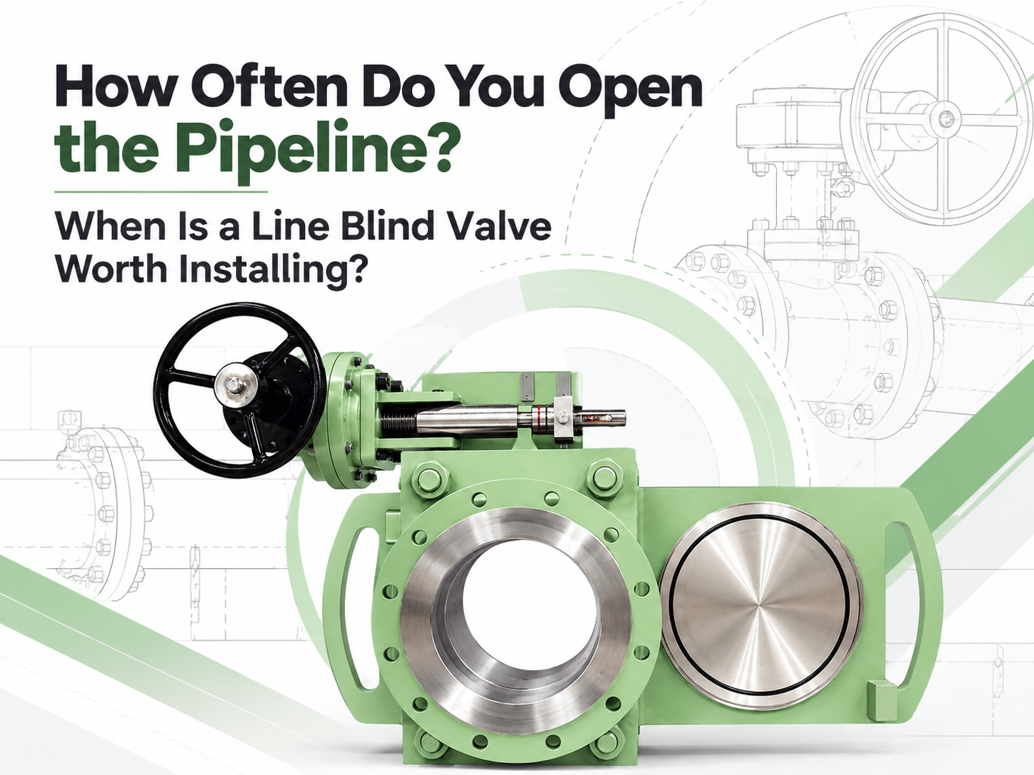
라인 블라인드 밸브는 파이프라인을 연간 여러 번 차단해야 하거나, 기존의 전환 작업으로 인해 수 시간의 가동 중단, 인양 작업 또는 유해 잔류물에 대한 상당한 노출이 발생하는 경우 평가해 볼 가치가 있습니다. 투자 회수를 보장하는 만능 작동 횟수 기준은 없습니다. 연간 두 번 작동하는 대형 중요 라인은 투자가 정당화될 수 있는 반면, 월 단위로 작동하는 소형의 접근이 쉬운 라인은 그렇지 않을 수 있습니다. 이 결정은 빈도만이 아니라 각 완전 격리 이벤트의 비용과 리스크를 기반으로 이루어져야 합니다. ‘연간 2회 작동’이라는 표준 규칙은 없습니다 일부 공급업체는 연간 1~2회의 전환을 스크리닝 임계값으로 사용합니다. 이는 논의의 시작점이 될 수는 있지만 엔지니어링 규칙은 아닙니다. 빈도는 DN50 유틸리티 라인과 DN600 공정 가스 메인 라인에서 매우 다른 결과를 가져옵니다. 사전 검토를 위해 다음 대역은 필수가 아니지만 유용합니다: 차단 빈도 초기 해석 주요 정비(턴어라운드)당 1회 이하 분리형 블라인드 또는 스펙터클 블라인드가 경제적인 경우가 많습니다. 연간 1~3회 인건비, 인양, 중단 시간 및 매체 리스크를 신중하게 비교하십시오. 분기별 내지 월별 A 퀵액션 라인 블라인드(은)는 일반적으로 강력한 후보입니다. 주간 또는 더 빈번함 목적에 맞게 제작되거나 자동화된 격리는 상세한 검토가 필요하며, 라인 블라인드가 요구되는 사이클 작업에 적합한지 확인해야 합니다. 모든 작업에 비계, 크레인, 여러 명의 배관공 또는 오랜 생산 중단이 필요한 경우, 낮은 작동 빈도에서도 설치를 뒷받침할 수 있습니다. 반대로, 공정이 압력, 온도, 재질 또는 유지보수 요구 사항을 수용할 수 없는 경우 잦은 작동이라도 라인 블라인드를 정당화하지 못합니다. 완전한 전환 작업 횟수 산정 전통적인 블라인딩 작업은 단순히 판을 이동하는 것 이상입니다. 라인이 안전해진 후 작업자들은 볼트를 풀고, 플랜지 조인트를 벌리고, 블라인드 또는 스페이서를 다루고, 개스킷을 교체하고, 정렬을 복원하고, 조인트를 조이고 누출 점검을 완료합니다. 대형 규격의 경우 리깅 및 접근 장비가 추가됩니다. 퀵액션 라인 블라인드는 설치된 어셈블리 내부에 스펙터클 또는 슬라이딩 플레이트가 지지된 상태를 유지합니다. 제조업체 문헌에 따르면 기존 플랜지 작업에 필요한 맨아워(man-hour) 대신 몇 분 만에 1명이 전환 작업을 수행할 수 있다고 흔히 보고됩니다. 이러한 수치는 스크리닝에 유용하지만, 프로젝트 계산에는 플랜트 자체의 절차
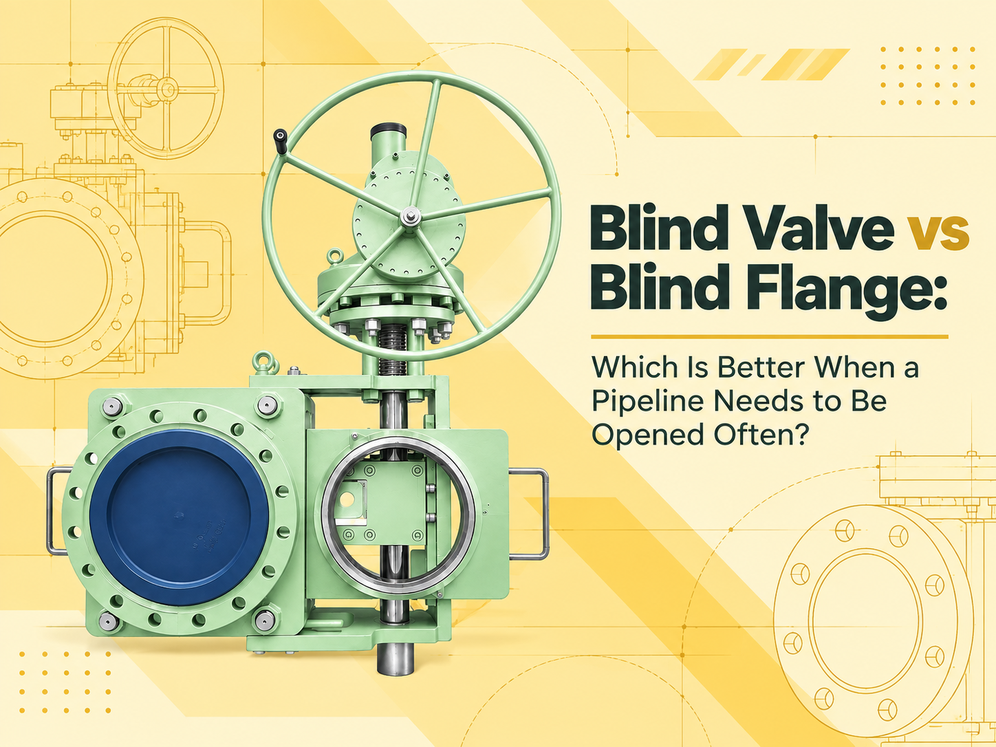
파이프라인을 자주 개방하고 확실하게 차단해야 하는 경우, 라인 블라인드 밸브가 일반적으로 더 나은 선택입니다. 이 밸브는 블라인드 메커니즘을 영구적으로 설치된 상태로 유지하며, 작업자가 볼트로 고정된 끝단 마개를 반복적으로 제거할 필요 없이 개방 위치와 차단 위치를 전환할 수 있게 해줍니다. 블라인드 플랜지는 비용이 저렴하고 움직이는 부품이 적지만, 장기간 닫힌 상태로 유지될 파이프 끝을 막는 데 더 적합합니다. 이 답변은 “블라인드 플랜지”가 파이프나 노즐 끝에 볼트로 고정된 단단한 플랜지를 의미한다고 가정합니다. 두 플랜지 사이에 설치되는 스펙터클 블라인드나 탈착식 스페이드는 유사한 고체 금속 차단 장벽을 형성하지만, 이는 다른 장치입니다. 잦은 개방은 비용 계산을 변화시킵니다 구매 가격 면에서는 블라인드 플랜지가 유리합니다. 구조가 단순하고 유지보수는 주로 플랜지 면, 개스킷, 스터드 및 너트를 점검하는 것으로 제한됩니다. 가끔 있는 정기 보수 기간에만 마개를 제거한다면, 이러한 단순함을 능가하기는 어렵습니다. 반복적인 개방은 상황을 바꿉니다. 블라인드 플랜지를 제거하려면 라인을 차단하고, 압력을 낮추고, 배수 또는 퍼지 작업을 수행한 뒤 안전을 확인해야 합니다. 그런 다음 볼트를 풀고, 플랜지를 지지하고, 밀봉 면을 분리해야 합니다. 더 큰 플랜지의 경우 리프팅 장비가 필요할 수 있습니다. 재조립 시에는 새 개스킷을 사용하고, 볼트를 제어된 방식으로 조이며, 누출 테스트를 수행해야 합니다. 이러한 단계 중 특별한 것은 없지만, 이를 반복하면 저비용 부품이 노동 집약적인 운영 방식으로 변하게 됩니다. 라인 블라인드 밸브 역시 승인된 설계 및 운영 절차에 별도의 명시가 없는 한, 위치를 변경하기 전에 라인을 차단하고 압력을 낮춰야 합니다. 이 밸브의 장점은 기계적 취급에 있습니다. 플레이트, 스페이서 또는 슬라이딩 요소가 본체 내에 고정되어 있으며, 메커니즘이 밀봉 면을 분리, 이동 및 재고정합니다. 수동 기어는 적절한 작동 힘에 적합할 수 있으며, 대형 사이즈나 원격 작동의 경우 전기, 공압 또는 유압 구동 방식이 정당화될 수 있습니다. 블라인드 밸브는 취급을 줄여주지만 유지보수할 장비를 추가합니다 잦은 전환의 경우, 블라인드 밸브는 작업을 단축하고 무거운 플레이트, 볼트 및 개스킷의 반복적인 취급을 줄일 수 있습니다. 개방 또는 폐쇄 위치는 일반적으로 외부 플레이트나 위치 표시기를 통해 확인할 수 있어 현장 검증에 도움이 됩니다. 또í•
지불:
30% T/T When Order, 70% T/T Before Shipment제품 원산지:
China색:
Customization배송 포트:
Shanghai China리드 타임:
30~55 days Ex Works After Order ConfirmationMaterial:
Stainless SteelMethod of Operation:
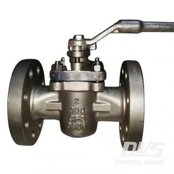
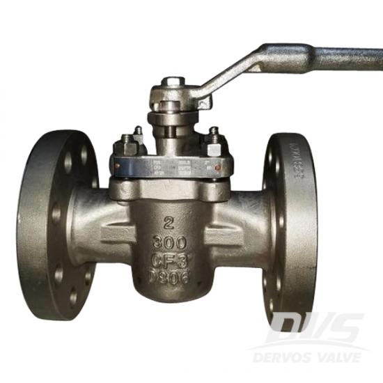
Leverptfe 슬리브 플러그 밸브는 cf3 본체로 만들어지며 api 6d에 따라 플러그됩니다. 밸브는 감소 된 포트 및 우수한 밀봉 성능을 특징으로합니다. 이 유형의 밸브를 비 윤활식 플러그 밸브 또는 자체 윤활식 플러그 밸브라고합니다.
빠른 세부 사항
|
유형 |
플러그 판막 |
|
크기 |
2 인치 |
|
설계 압력 |
300 파운드 |
|
구성 |
자체 윤활 타입, 슬리브 타입, 비 윤활 타입, 소프트 시트 |
|
연결 타입 |
플랜지 |
|
조작 |
지렛대 조작 |
|
디자인 코드 |
API 599, API 6D |
|
면 대면 |
저 같은 b16.10 |
|
연결 종료 |
저 같은 b16.5 |
|
압력 및 온도 |
저 같은 b16.34 |
|
테스트 & amp; 검사 |
API 598 |
|
바디 재료 |
cf3 |
|
온도 범위 |
-29 ℃ ~ + 120 ℃ |
|
신청 |
물, 석유 가스 |
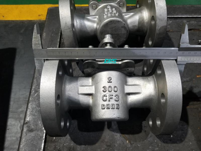
치수 확인
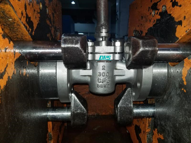
정수압 테스트
에 관심이 있다면 우리의 제품과한 자세한 내용을 알고 싶다면,메시지를 남겨주십시오 여기,우리가 응답할 것입니다 당신은 빨리 우리가 할 수 있습니다.
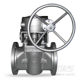
6 인치 슬리브 플러그 밸브는 비 윤활 디자인과 부드러운 시트로 구성되어 있습니다. 전체 포트 플러그 밸브는 클래스 150 플랜지 연결을 사용하여 API 6d에 따라 탄소강 몸체와 PTFE 시트로 제작됩니다. 빠른 세부 사항 유형 플러그 판막 크기 6 인치 설계 압력 150 파운드 구성 자체 윤활 타입, 슬리브 타입, 소프트 시트 연결 타입 rf 플랜지 조작 변속 장치 조작 디자인 코드 API 599 면 대면 저 같은 b16.10 연결 종료 저 같은 b16.5 압력 및 온도 저 같은 b16.34 테스트 & amp; 검사 API 598 바디 재료 a216 wcb 온도 범위 -29 ℃ ~ + 425 ℃ 신청 물, 석유 가스 소재 & amp; 치수 아니 부품 이름 탄소 강철에서 ASTM으로 스테인리스 강철에서 ASTM으로 wcb lcb cf8 cf8m cf3 cf3m 1 신체 a216 화장실 a350 lcb a351 cf8 a351 cf8m a351 cf3 a351 cf3m 2 보닛 a216 화장실 a350 lcb a351 cf8 a351 cf8m a351 cf3 a351 cf3m 삼 플러그 a105 a182 f304 a351 cf8 a351 cf8m a351 cf3 a351 cf3m 4 줄기 a182 f6 a182 f6 a182 f304 a182 f316 a182 f304l a182 f316l 5 좌석 링 ptfe 6 틈 메우는 물건 ptfe 또는 스테인리스 및 흑연 7 줄기 좌석 ptfe ptfe ptfe ptfe ptfe ptfe 8 작은 봄 17-17ph 9 작은 공 a182 f304 또는 a182 f316 10 선 a182 f6 a182 f6 a182 f304 a182 f316 a182 f304l a182 f316l 11 글 랜드 플랜지 a216 화장실 a350 lcb a351 cf8 a351 cf8m a351 cf3 a351 cf3m 12 줄기 포장 ptfe 또는 흑연 13 보닛 볼트 a193 b7 또는 a320 l7 또는 a320 b8 또는 a193 b8m 14 보닛 너트 a194 2 시간 또는 a194 4 또는 a194 8 클래스 150 dn mm 15 20 25 40 50 65 80 100 150 200 250 300 nps 에 1/2 3/4 1 1 1/2 2 2 1/2 삼 4 6 8 10 12 l (rf) mm 108 117 127 165 178 191 203 229 394 457 533 610 에 4.25 4.6 5 6.5 7 7.5 8 9 15.5 18 21 24 l1 (bw) mm 140 152 165 190 216 241 283 305 457 521 559 635 에 5.5 6 6.5 7.48 8.5 9.5 11.13 12 18 20.5 22 25 l2 (rtj) mm 119 129.7 139.7 178 191 203 216 241 406 470 546 622 에 4.69 5.11 5.5 6.9 7.5 8 8.5 905 16 18.5 21.5 24.5 h mm 59 63 75 92 153 165 195 213 272 342 495 580 에 2.3 2.5 2.95 3.74 6.02 6.5 7.68 8.39 10.7 13.5 19.5 22.85 d (w) mm 130 130 160 230 400 400 600 850 1100 1500 년 350 * 350 * 에 5.1 5.1 6.3 9 15.74 15.74 23.62 33.46 43.3 59 13.8 13.8 무게 (kg) rf 2.3 삼 4.5 7 15 20 25 40 97 160 240 390 bw 2.0 2.5 3.8 5.8 12 17 21 36 92.8 154 227 365
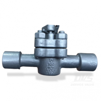
이 1 / 2 인치 플러그 밸브는 A216 API598.With 에 따른 WCB유지 보수가 거의 필요하지 않고 문제가없는 작동, 높은 무결성 버블 타이트 씰은 인라인 그리고 대기.
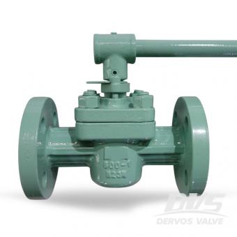
1 인치 슬리브 형 플러그 밸브는 api 599에 따라 a216 wcb로 만들어졌습니다. PTFE 시트 덕분에 밸브는 우수한 밀봉 및 부식 방지 성능을 제공합니다. 밸브는 180도 미만의 작업 조건에서 가능합니다.
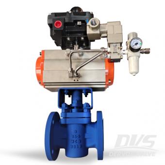
무 윤활 슬리브 플러그 밸브에는 최신 PPL 좌석 디자인. 함께 유지 보수가 거의 필요하지 않고 문제가없는 작동, 3 인치 150lb 밸브는 높은 무결성을 보장합니다. 씰.
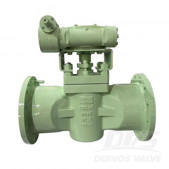
DN250 PN25 플러그 밸브는 API599 표준에 따라 만들어집니다. 밸브 본체는 A216 WCB로 제작되었습니다. 그것은 부드러운 밀봉 플러그 밸브의 구조적 특성을 가지고 있습니다. 연결 모드는 RF입니다. 그리고 터빈 작동 모드가 있습니다.
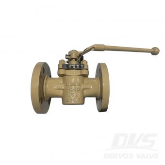
DN50 PN40 플러그 밸브는 API 599 표준에 따라 제작되었습니다. 밸브 본체는 A216 WCB로 만들어졌습니다. Ferrule type, 감소된 직경의 구조적 특징을 가지고 있습니다. 연결 모드는 RF입니다. 그리고 레버 조작 모드가 있습니다.
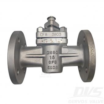
DN50 PN16 슬리브형 플러그 밸브는 API599 표준에 따라 제작되었습니다. 밸브 본체는 CF8 재질입니다. 카트리지 타입, 소프트 시트 구조적 특징을 가지고 있습니다. 연결 방식은 EN1092-1 B입니다. 그리고 레버가 있습니다.작동 방식. 제품 매개변수 유형 슬리브형 플러그 밸브 크기 DN50 압력 PN16 연결 EN1092-1 B 작동 레버 작동식 본체 재질 CF8 설계 표준 API 599 면간 거리 DIN 3202F1 단부 연결 EN1092-1 시험 및 검사 코드 EN12266 온도 -29 ~ 150°C 적용 매체 물, 오일 및 가스 특징 1. 슬리브형 플러그 설계: 정기적인 윤활 필요성을 제거하면서 낮은 마찰 작동과 확실한 차단을 제공합니다. 2. 레버 작동식 CF8 스테인리스 스틸: 산업용 유체 서비스를 위한 내식성과 신속한 쿼터 턴 수동 제어를 제공합니다. 기술 도면 치수 검사 압력 테스트 명판 및 포장 검사 보고서