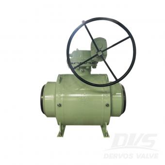
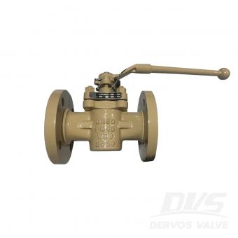
An API 602 forged gate valve is used for compact, small-bore gate valve service in petroleum, natural gas, chemical, power, and industrial piping. To specify the right design, confirm size, pressure class, material, bonnet type, end connection, port type, trim, seat, testing standard, and service conditions. What Is an API 602 Forged Gate Valve? An API 602 forged gate valve is a compact steel gate valve manufactured to API 602 requirements. API 602 covers gate, globe, and check valves for sizes DN 100 / NPS 4 and smaller in petroleum and natural gas industry applications. Unlike large cast steel gate valves, forged gate valves are usually selected for smaller piping systems where pressure, temperature, vibration, or compact installation matters. Forged construction provides a dense material structure, which is useful for high-pressure and critical service. In simple terms, API 602 is often the better fit when the line is small but the service is demanding. When Should You Use an API 602 Forged Gate Valve? Use an API 602 forged gate valve when the application requires reliable isolation in a compact piping system. It is commonly used in refineries, chemical plants, power plants, oil and gas facilities, steam lines, vents, drains, and utility systems. Typical use cases include: ● Small-bore high-pressure lines ● Steam and condensate service ● Process isolation ● Skid-mounted systems ● Drain and vent connections ● Instrument and auxiliary piping ● Oil, gas, and petrochemical service For larger line sizes or heavy-duty cast steel applications, API 600 may be more appropriate. API 602 and API 600 should not be treated as interchangeable standards. Key Design Choices to Specify Do not specify an API 602 forged gate valve only by size and pressure class. The purchase requirement should define the full valve design. Important items include: Item What to Confirm Size DN / NPS size and bore requirement Pressure class Class 800, 1500, 2500, or project requirement Material A105, F304, F316, F11, F22, LF2, or other grade Bonnet type Bolted bonnet, welded bonnet, or pressure seal End connection Socket weld, threaded, butt weld, or flanged Port Full port or regular port Trim Stem, wedge, seat, and hardfacing material Operation Handwheel, gearbox, or actuator if required Testing API 598 or project-specified testing These details affect sealing, pressure capability, maintainability, and installation. Bonnet and End Connection Selection Bonnet type should match pressure, temperature, and maintenance needs. Bolted bonnet designs are common and easier to service. Welded bonnet designs reduce potential leakage paths but are less convenient to disassemble. Pressure seal bonnets may be considered for higher-pressure service, depending on the design and project requirement. End connection is equally important. Socket weld ends are common for small-bore forged valves. Threaded ends may be...
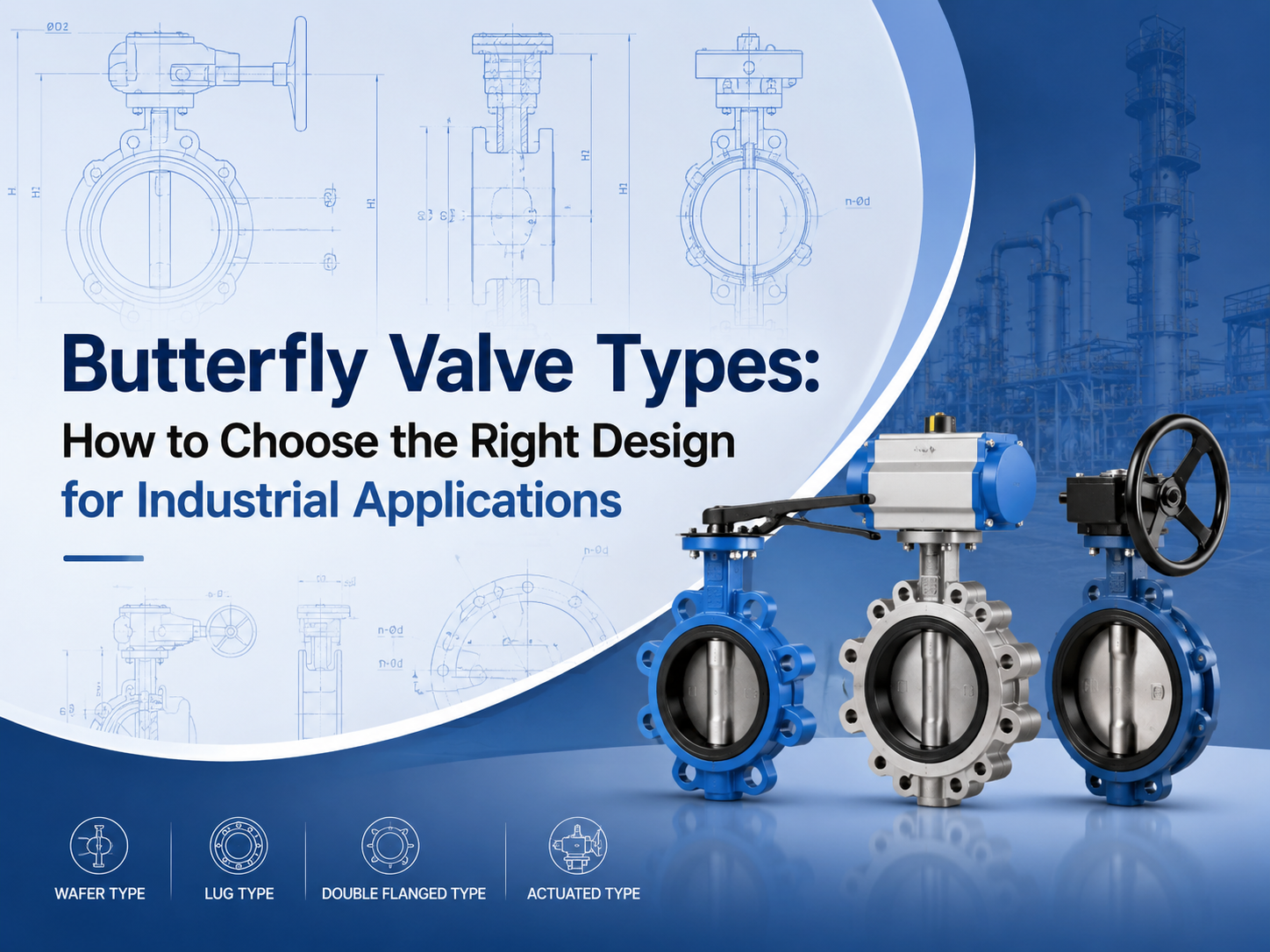
주요 버터플라이 밸브 유형에는 동심형, 이중 편심형, 삼중 편심형, 웨이퍼형, 러그형, 플랜지형, 소프트 시트형, 금속 시트형, 수동식, 공압식 및 전동식 버터플라이 밸브가 포함됩니다. 적절한 선택은 압력, 온도, 유체, 누설 요구 사항, 설치 공간 및 작동 빈도에 따라 달라집니다. 주요 버터플라이 밸브 유형은 무엇인가요? 버터플라이 밸브는 일반적으로 디스크 설계, 본체 연결 방식, 시트 재질 및 구동 방식에 따라 분류됩니다. 이 분류가 중요한 이유는 두 밸브가 모두 버터플라이 밸브라고 불리더라도 사용 한계가 매우 다를 수 있기 때문입니다. 버터플라이 밸브는 회전하는 디스크를 사용하여 유량을 차단하거나 조절합니다. 컴팩트한 구조, 가벼운 무게 및 90도 회전 작동 방식 때문에 수처리, 발전소, 화학 공정, HVAC, 해양 시스템 및 일반 산업용 배관에 널리 사용됩니다. 구매자에게 핵심 질문은 단순히 “어느 유형이 더 저렴한가?”가 아닙니다. “어느 유형이 실제 압력, 온도, 유체 및 밀봉 요구 사항을 처리할 수 있는가?”입니다. 동심형 버터플라이 밸브 A 동심형 버터플라이 밸브는 밸브 본체와 디스크의 중심선에 스템이 위치합니다. 센터라인 버터플라이 밸브라고도 합니다. 이 유형은 일반적으로 저압 및 일반 서비스 용도에 사용되며, 특히 물, 공기 및 비공격성 유체에 적합합니다. 구조가 간단하고 경제적이며 유지보수가 쉽습니다. 제한점은 시트 마모입니다. 개폐 과정에서 디스크는 이동하는 동안 상당 부분 소프트 시트와 접촉 상태를 유지합니다. 더 높은 압력, 더 높은 온도 또는 더 엄격한 차단 요구 사항에서는 이중 편심형 또는 삼중 편심형 설계가 더 적합한 경우가 많습니다. 이중 편심형 버터플라이 밸브 A 이중 편심형 버터플라이 밸브는 디스크와 시트 사이의 마찰을 줄이기 위해 두 개의 편심 구조를 사용합니다. 이는 밀봉 성능을 향상시키고 기본 동심형 설계보다 사용 수명을 연장하는 데 도움이 됩니다. 이중 편심형 버터플라이 밸브는 석유 및 가스, 급수, 발전 및 화학 시스템을 포함한 중압 산업용 서비스에 자주 선택됩니다. 완전한 금속 시트 삼중 편심형 설계까지는 필요하지 않지만 더 나은 내구성이 필요한 경우 유용합니다. 이 유형은 고성능 버터플라이 밸브라고도 흔히 불립니다. 선택 전에 구매자는 압력 등급, 시트 재질, 축 밀봉 설계 및 예상 작동 빈도를 확인해야 합니다. 삼중 편심형 버터플라이 밸브 A 삼중 편심형 버터플라이 밸브는 더 발전된 밀봉 구조를 만들기 위해 세 번째 기�
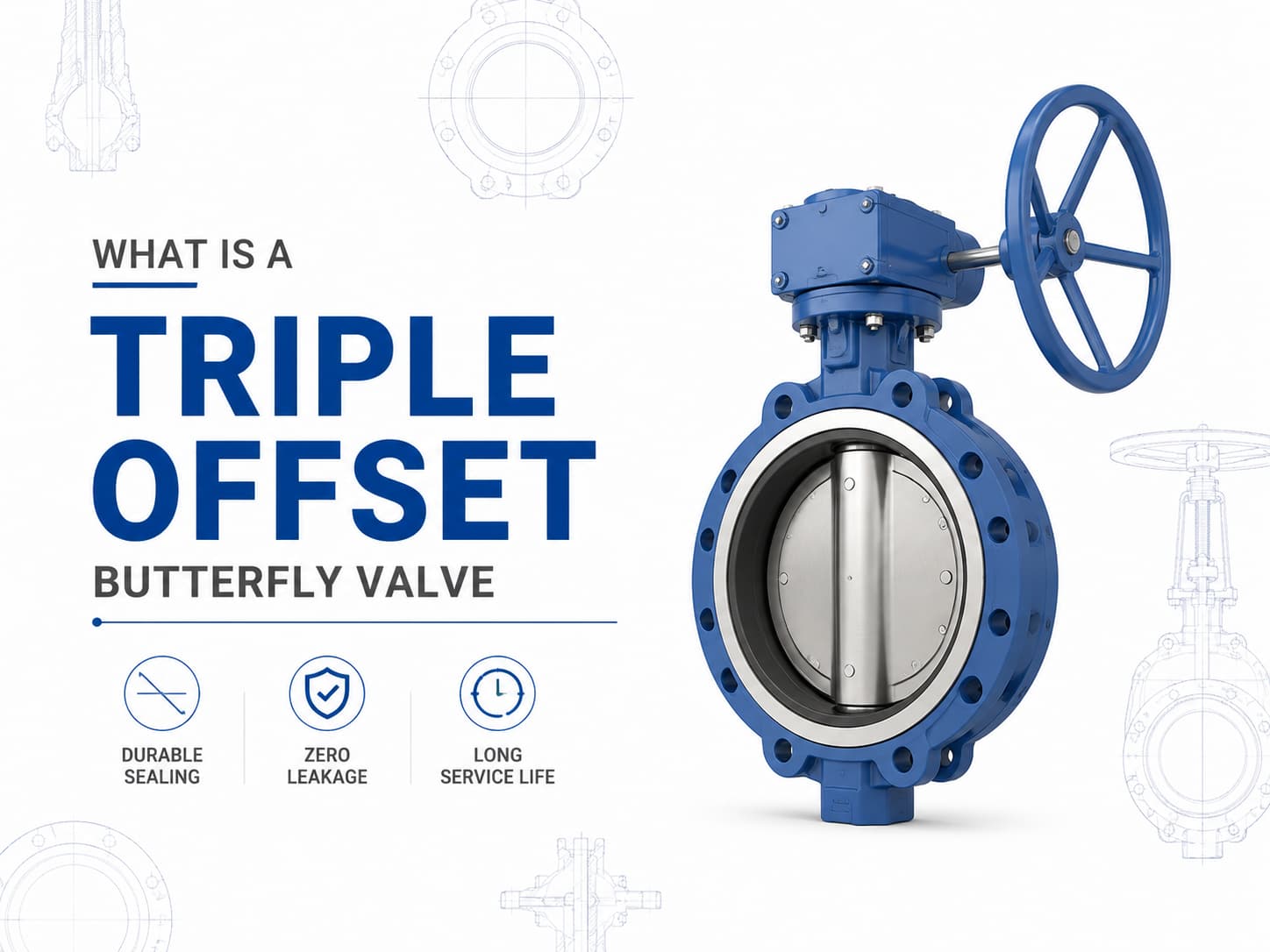
A 트리플 오프셋 버터플라이 밸브은 기존의 탄성 시트형 또는 더블 오프셋 버터플라이 밸브가 압력, 온도 또는 누설 요구사항을 충족하지 못하는 응용 분야를 위해 설계된 고성능 차단 밸브입니다. 3중 오프셋 밀봉 설계를 사용하여 작동 중 디스크와 시트 사이의 마찰을 줄인 금속 대 금속 밀봉 메커니즘을 구현하므로 오일 및 가스, 석유화학, 발전, LNG, 증기 및 산업 공정 시스템과 같은 까다로운 서비스에 적합합니다. 트리플 오프셋 버터플라이 밸브 설계 및 작동 원리 디스크와 시트의 중심선에 샤프트가 위치하는 동심형 버터플라이 밸브와 달리, 트리플 오프셋 버터플라이 밸브은 세 가지 독립적인 기하학적 오프셋을 적용합니다. 첫 번째 오프셋은 샤프트를 밸브 본체의 중심선에서 이동시키고, 두 번째 오프셋은 샤프트를 배관 중심선에서 이동시키며, 세 번째 오프셋은 원형 밀봉 형상 대신 원뿔형 밀봉 표면을 적용합니다. 이 형상은 회전이 시작된 직후 디스크가 시트에서 떨어져 이동하도록 하여 밀봉 표면 사이의 마찰을 제거합니다. 이 설계의 주요 장점은 밀봉력이 연질 재료의 지속적인 압축이 아니라 토크에 의해 생성된다는 점입니다. 고온 서비스가 필요한 경우, 엘라스토머 시트는 높은 온도에서 열화될 수 있으므로 금속 시트형 트리플 오프셋 버터플라이 밸브이 자주 선호됩니다. 매체에 마모성 입자 또는 부식성 화학물질이 포함된 경우, 장기간 작동 중 침식, 부식 및 누설을 방지하기 위해 디스크, 시트 및 본체의 재질 선택이 매우 중요합니다. 트리플 오프셋 버터플라이 밸브 표준 및 재질 트리플 오프셋 버터플라이 밸브는 일반적으로 API 609, EN 593 및 ISO 5752와 같은 표준에 따라 제조되며, 설계 요구사항에 따라 압력 등급은 Class 150부터 Class 600 이상까지 다양합니다. 일반적인 재질에는 탄소강, 스테인리스강, 듀플렉스 스테인리스강, 알루미늄 청동 및 니켈 기반 합금이 포함됩니다. 부식성 해수 응용 분야에서는 C95500 또는 C95800과 같은 알루미늄 청동 합금이 선택될 수 있으며, 사워 서비스 응용 분야에서는 NACE MR0175/ISO 15156 요구사항을 준수하는 재질이 필요할 수 있습니다. 트리플 오프셋 버터플라이 밸브 밀봉 성능 및 누설 제어 트리플 오프셋 버터플라이 밸브의 밀봉 성능은 밀봉 링, 시트 표면 마감, 작동 토크 및 재질 호환성 간의 상호작용에 따라 결정됩니다. 밀봉 표면은 최종 폐쇄 위치에서만 접촉하므로 기존 버터플라이 밸브 설계와 비교하여 기계적 마모가 크게 감소합니다. 중요한 차단 작업에서 제로 누설이
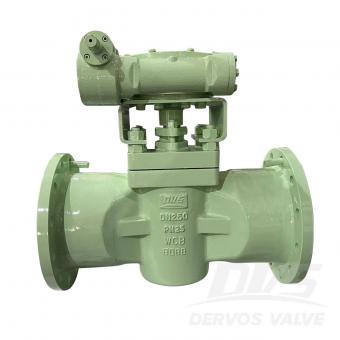
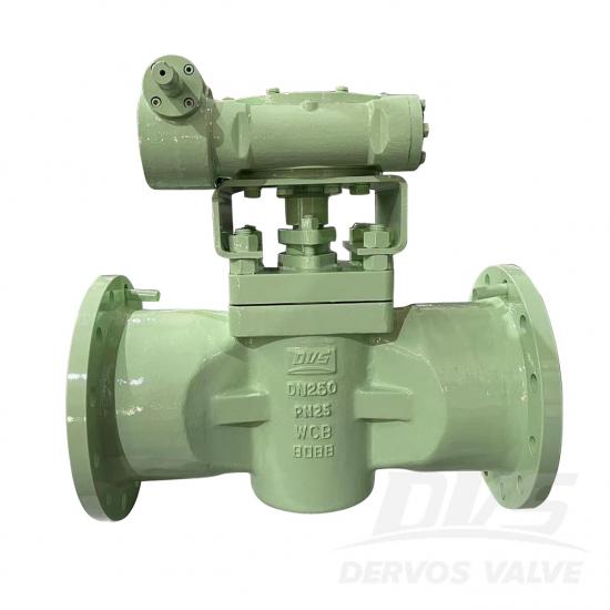
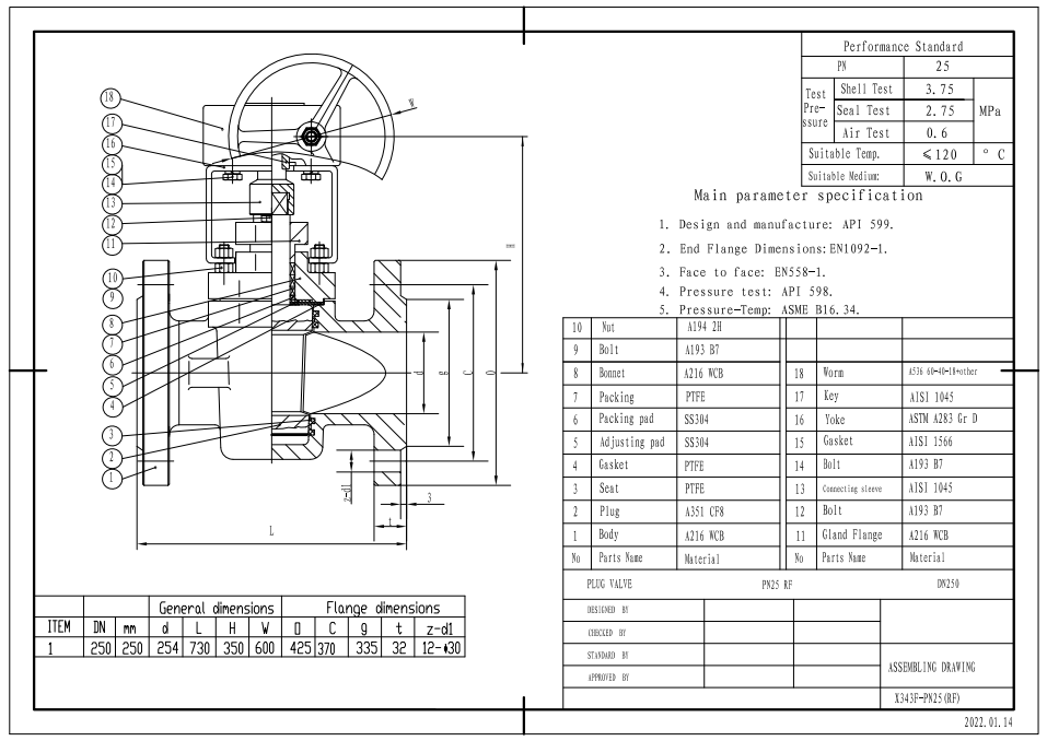
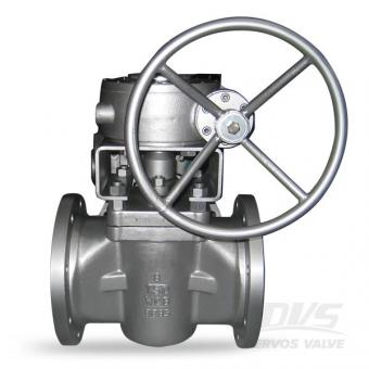
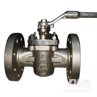
DN250 PN25 플러그 밸브는 API599 표준에 따라 만들어집니다. 밸브 본체는 A216 WCB로 제작되었습니다. 그것은 부드러운 밀봉 플러그 밸브의 구조적 특성을 가지고 있습니다. 연결 모드는 RF입니다. 그리고 터빈 작동 모드가 있습니다.
지불:
30% when order confirmed, 70% before shipment제품 원산지:
China색:
Customization배송 포트:
Shanghai, China리드 타임:
30~60 days Ex Works after order confirmationMaterial:
A216 WCBMethod of Operation:
Turbine Operation제품 설명
| 유형 |
플러그 밸브 |
| 크기 |
DN250 |
| 압력 |
PN25 |
| 연결 |
RF |
| 작업 |
터빈 작동 |
| 본체 재질 |
A216 WCB |
| 디자인 규범 |
API 599 |
| 끝단 플랜지 치수 |
EN1092-1 |
| 면 대면 |
EN558-1 |
| 압력 테스트 |
API 598 |
| 압력 온도 |
ASME B16.34 |
| 온도 |
≤ 120°C |
| 적용 가능한 매체 |
물, 석유 및 가스 |
특징
1. 낮은 저항, 쉽고 빠른 개폐;
2. 간단한 구조, 편리한 작동 및 낮은 유체 저항.
기술 도면
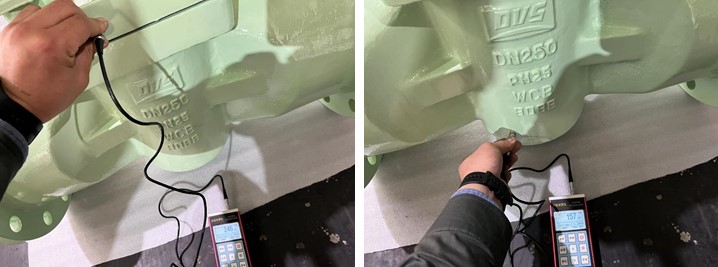
치수 확인
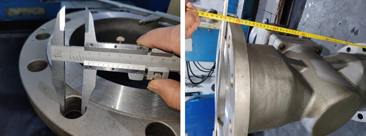
압력 테스트
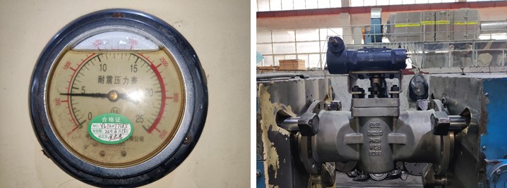
그림
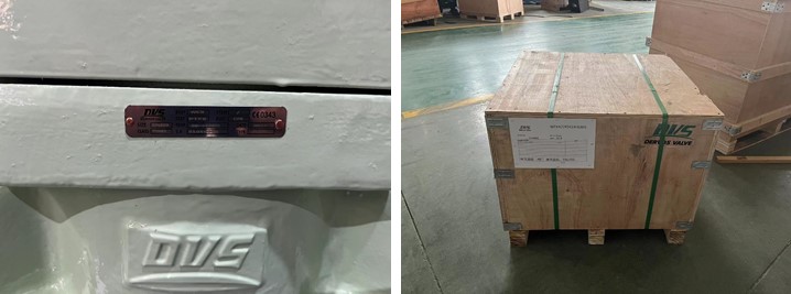
명판 및 포장
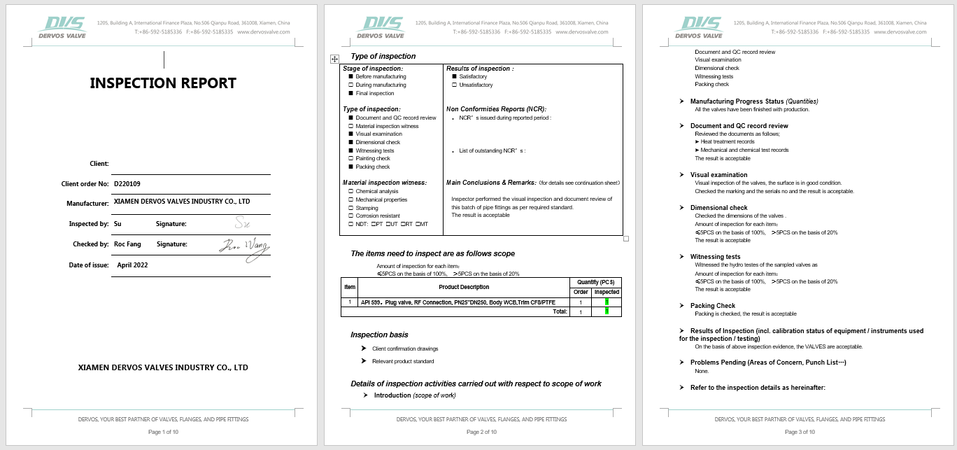
검사 보고서
에 관심이 있다면 우리의 제품과한 자세한 내용을 알고 싶다면,메시지를 남겨주십시오 여기,우리가 응답할 것입니다 당신은 빨리 우리가 할 수 있습니다.
6 인치 슬리브 플러그 밸브는 비 윤활 디자인과 부드러운 시트로 구성되어 있습니다. 전체 포트 플러그 밸브는 클래스 150 플랜지 연결을 사용하여 API 6d에 따라 탄소강 몸체와 PTFE 시트로 제작됩니다. 빠른 세부 사항 유형 플러그 판막 크기 6 인치 설계 압력 150 파운드 구성 자체 윤활 타입, 슬리브 타입, 소프트 시트 연결 타입 rf 플랜지 조작 변속 장치 조작 디자인 코드 API 599 면 대면 저 같은 b16.10 연결 종료 저 같은 b16.5 압력 및 온도 저 같은 b16.34 테스트 & amp; 검사 API 598 바디 재료 a216 wcb 온도 범위 -29 ℃ ~ + 425 ℃ 신청 물, 석유 가스 소재 & amp; 치수 아니 부품 이름 탄소 강철에서 ASTM으로 스테인리스 강철에서 ASTM으로 wcb lcb cf8 cf8m cf3 cf3m 1 신체 a216 화장실 a350 lcb a351 cf8 a351 cf8m a351 cf3 a351 cf3m 2 보닛 a216 화장실 a350 lcb a351 cf8 a351 cf8m a351 cf3 a351 cf3m 삼 플러그 a105 a182 f304 a351 cf8 a351 cf8m a351 cf3 a351 cf3m 4 줄기 a182 f6 a182 f6 a182 f304 a182 f316 a182 f304l a182 f316l 5 좌석 링 ptfe 6 틈 메우는 물건 ptfe 또는 스테인리스 및 흑연 7 줄기 좌석 ptfe ptfe ptfe ptfe ptfe ptfe 8 작은 봄 17-17ph 9 작은 공 a182 f304 또는 a182 f316 10 선 a182 f6 a182 f6 a182 f304 a182 f316 a182 f304l a182 f316l 11 글 랜드 플랜지 a216 화장실 a350 lcb a351 cf8 a351 cf8m a351 cf3 a351 cf3m 12 줄기 포장 ptfe 또는 흑연 13 보닛 볼트 a193 b7 또는 a320 l7 또는 a320 b8 또는 a193 b8m 14 보닛 너트 a194 2 시간 또는 a194 4 또는 a194 8 클래스 150 dn mm 15 20 25 40 50 65 80 100 150 200 250 300 nps 에 1/2 3/4 1 1 1/2 2 2 1/2 삼 4 6 8 10 12 l (rf) mm 108 117 127 165 178 191 203 229 394 457 533 610 에 4.25 4.6 5 6.5 7 7.5 8 9 15.5 18 21 24 l1 (bw) mm 140 152 165 190 216 241 283 305 457 521 559 635 에 5.5 6 6.5 7.48 8.5 9.5 11.13 12 18 20.5 22 25 l2 (rtj) mm 119 129.7 139.7 178 191 203 216 241 406 470 546 622 에 4.69 5.11 5.5 6.9 7.5 8 8.5 905 16 18.5 21.5 24.5 h mm 59 63 75 92 153 165 195 213 272 342 495 580 에 2.3 2.5 2.95 3.74 6.02 6.5 7.68 8.39 10.7 13.5 19.5 22.85 d (w) mm 130 130 160 230 400 400 600 850 1100 1500 년 350 * 350 * 에 5.1 5.1 6.3 9 15.74 15.74 23.62 33.46 43.3 59 13.8 13.8 무게 (kg) rf 2.3 삼 4.5 7 15 20 25 40 97 160 240 390 bw 2.0 2.5 3.8 5.8 12 17 21 36 92.8 154 227 365
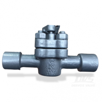
ptfe 슬리브 플러그 밸브는 cf3 본체로 만들어지며 api 6d에 따라 플러그됩니다. 밸브는 감소 된 포트 및 우수한 밀봉 성능을 특징으로합니다. 이 유형의 밸브를 비 윤활식 플러그 밸브 또는 자체 윤활식 플러그 밸브라고합니다. 빠른 세부 사항 유형 플러그 판막 크기 2 인치 설계 압력 300 파운드 구성 자체 윤활 타입, 슬리브 타입, 비 윤활 타입, 소프트 시트 연결 타입 플랜지 조작 지렛대 조작 디자인 코드 API 599, API 6D 면 대면 저 같은 b16.10 연결 종료 저 같은 b16.5 압력 및 온도 저 같은 b16.34 테스트 & amp; 검사 API 598 바디 재료 cf3 온도 범위 -29 ℃ ~ + 120 ℃ 신청 물, 석유 가스 치수 확인 정수압 테스트
이 1 / 2 인치 플러그 밸브는 A216 API598.With 에 따른 WCB유지 보수가 거의 필요하지 않고 문제가없는 작동, 높은 무결성 버블 타이트 씰은 인라인 그리고 대기.
1 인치 슬리브 형 플러그 밸브는 api 599에 따라 a216 wcb로 만들어졌습니다. PTFE 시트 덕분에 밸브는 우수한 밀봉 및 부식 방지 성능을 제공합니다. 밸브는 180도 미만의 작업 조건에서 가능합니다.
무 윤활 슬리브 플러그 밸브에는 최신 PPL 좌석 디자인. 함께 유지 보수가 거의 필요하지 않고 문제가없는 작동, 3 인치 150lb 밸브는 높은 무결성을 보장합니다. 씰.
DN50 PN40 플러그 밸브는 API 599 표준에 따라 제작되었습니다. 밸브 본체는 A216 WCB로 만들어졌습니다. Ferrule type, 감소된 직경의 구조적 특징을 가지고 있습니다. 연결 모드는 RF입니다. 그리고 레버 조작 모드가 있습니다.