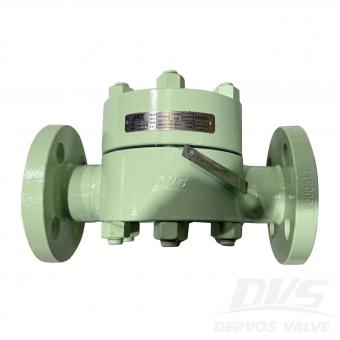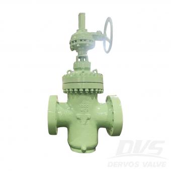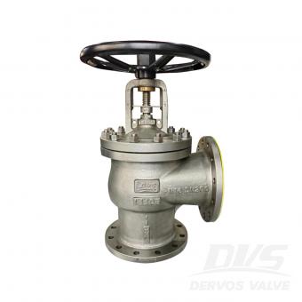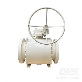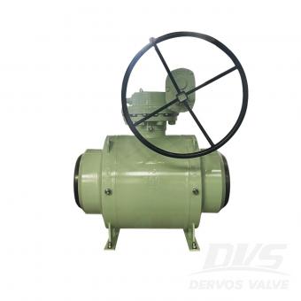
1. Suzhou Neway Valve Co., Ltd. — NEWAY NEWAY is one of China's most internationally recognized industrial valve manufacturers. Its product range includes ball valves, gate valves, globe valves, check valves, butterfly valves, cryogenic valves, subsea valves, and other engineered valve solutions. The company has strong experience in oil and gas, LNG, petrochemical, offshore, and power applications. Best suited for: large-scale energy projects and severe-service applications. 2. CNNC Sufa Technology Industry Co., Ltd. CNNC SUFA is well known for its experience in nuclear power and other high-integrity industrial applications. The company has strong capabilities in material traceability, engineering control, testing, and specialized valve manufacturing. Its products are also used in petroleum, petrochemical, power, and chemical industries. Best suited for: nuclear power, high-integrity systems, and technically demanding projects. 3. DERVOS VALVE DERVOS VALVE supplies industrial valves to customers in oil and gas, petrochemical, power generation, water treatment, marine, and general industrial applications. Its main products include ball valves, gate valves, globe valves, check valves, butterfly valves, plug valves, knife gate valves, line blind valves, and strainers. DERVOS supports international standards such as API, ASME, EN, and DIN, and can provide carbon steel, stainless steel, alloy steel, duplex stainless steel, low-temperature steel, and other materials. One of its key strengths is flexibility. DERVOS can support mixed valve packages, small-to-medium quantities, customized specifications, and project-specific documentation. Best suited for: overseas distributors, EPC projects, customized valves, mixed orders, and flexible sourcing requirements. 4. Yuanda Valve Group Yuanda Valve Group is one of China's large-scale valve manufacturers with broad production capacity. Its product range includes gate valves, globe valves, check valves, butterfly valves, ball valves, and other general industrial valves. The company is widely involved in water supply, HVAC, municipal infrastructure, power, and industrial pipeline projects. Best suited for: large-volume standardized valve procurement and general industrial applications. 5. Jiangsu Shentong Valve Co., Ltd. Jiangsu Shentong focuses strongly on specialized valve applications in metallurgy, energy, nuclear power, and chemical industries. Its strength lies in engineered products for demanding operating conditions rather than only standard valve production. Best suited for: metallurgy, energy, chemical processing, and specialized industrial applications. 6. Chaoda Valves Group Co., Ltd. Chaoda Valves Group serves petroleum, chemical, natural gas, power, and other process industries. Its product range includes ball valves, gate valves, globe valves, check valves, butterfly valves, and special-purpose industrial valves. The company has experience with corro...
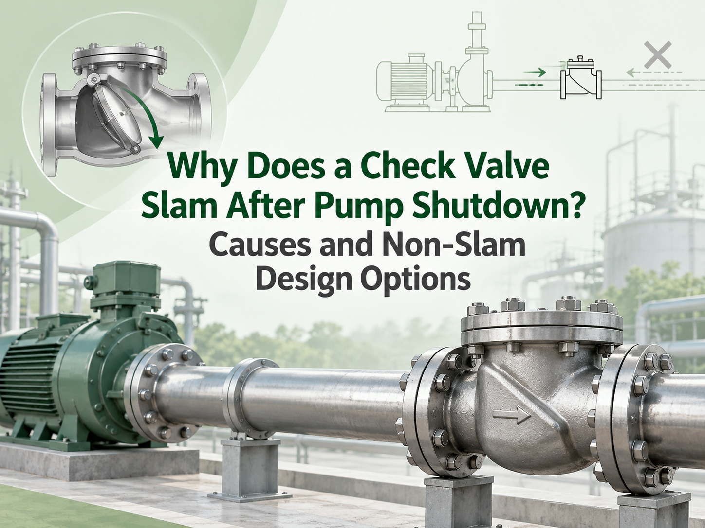
A check valve slams after pump shutdown when flow reverses before the closure member reaches its seat. The valve then stops that reverse velocity abruptly, creating a pressure wave through the piping. The damaging event is usually the rapid arrest of the liquid column, not simply the disc hitting the seat. A “non-slam” label alone is not a solution; the valve response must suit the system's flow deceleration. The Valve Is Closing Too Late for the Shutdown Transient When pump torque disappears, forward velocity falls. Static head, a pressurised common header or another running pump may then drive liquid back toward the stopped pump. If inertia and hinge friction keep a conventional swing disc open through zero flow, reverse velocity develops before the disc reaches its seat. High static lift, a steep rising main, short pump coast-down, parallel pumps and high initial velocity can accelerate this reversal. A long-stroke or high-inertia valve is more likely to lag. This is why the same valve may run quietly in one system and slam in another: nominal size and pressure class do not define shutdown behaviour. Confirm the Event Before Changing the Valve A single hard bang after shutdown points toward check-valve closure or another surge event. Continuous clicking during forward flow is chatter, which more often indicates unstable partial opening, pulsation or poor hydraulic sizing. Record the stop command, motor speed decay, flow direction and pressures on both sides of the valve on a common time base. A high-speed video of an external lever or position indicator can help show when the valve closes. For consequential systems, fast pressure logging is more reliable than sound alone. Inspect the hinge, shaft, spring and seat for friction, wear, deposits or damage, and verify the permitted installation orientation. Check pipe supports as well; the pressure wave may produce its loudest noise away from the valve. Non-Slam Designs Use Different Closing Strategies An axial-flow or nozzle check valve uses a light, centrally guided disc, short travel and spring assistance. It begins closing as forward flow falls, ideally seating before appreciable reversal. It is a strong candidate for rapid pump trips, but pressure loss, cracking pressure, minimum stable flow, orientation and tolerance of solids still matter. A spring-assisted dual-plate valve uses two lighter plates and shorter travel than a conventional swing disc. Its compact construction can improve response, but “dual plate” does not mean slam-free. Plate inertia, spring torque, size and mounting position remain relevant. Tilting-disc, resilient-hinge and spring-assisted swing designs reduce travel or assist closure while retaining a relatively open flow path. They can suit large water lines where energy loss matters, provided dynamic data supports the selected design and size. Large pumping mains ma...
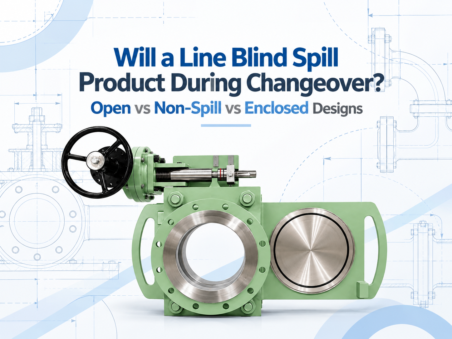
네, 개방형 라인 블라인드(line blind)는 개방 위치와 차단 위치 사이로 전환할 때 잔류 제품을 방출할 수 있습니다. 무유출 설계는 해당 잔류물을 사라지게 하는 것이 아니라, 부분적인 밀폐 공간에서 액체를 포집하여 드레인으로 유도합니다. 밀폐형 설계는 액체와 증기를 더 잘 제어할 수 있지만, 하우징, 드레인, 벤트 및 퍼지 연결부가 해당 용도에 맞게 설계된 경우에만 그렇습니다. 이러한 명칭 중 어느 것도 가압된 상태에서 블라인드를 이동시켜도 된다는 허가로 해석되어서는 안 됩니다. 전환 중에 제품이 유출될 수 있는 이유 라인 블라인드line blind가 완전히 클램핑되면 씰이 공정을 유지하고 솔리드 플레이트가 차단 위치에서 확실한 격리를 제공합니다. 전환 과정은 다릅니다. 스펙터클 플레이트나 슬라이딩 플레이트가 움직이기 전에 씰링면이 분리되어야 합니다. 그 간격 동안 바디 캐비티와 플레이트 통로가 주변 지역에 개방될 수 있습니다. 배관은 이미 차단되고, 압력이 제거되며, 비워져 있어야 하지만, "비워졌다"고 해서 완벽하게 건조하다는 뜻은 거의 아닙니다. 액체는 플레이트 위에 막 형태로 남아 있거나, 하부 본체에 고이거나, 배출이 잘 안 되는 배관 주머니에 고여 있을 수 있습니다. 가스 설비의 경우 인화성, 독성 또는 냄새가 나는 증기가 남을 수 있습니다. 따라서 배출되는 양은 라인 블라인드 그 자체만큼이나 배관 레이아웃과 차단 절차에 따라 좌우됩니다. 세 가지 디자인은 잔여물을 다르게 관리합니다 오픈 바디 디자인 노출된 플레이트 경로에서 잔류 액체가 임시 트레이나 작업 구역으로 떨어질 수 있으며, 증기는 국소적으로 확산됩니다. 이 배치는 용이한 접근과 육안 점검이 중요한 물, 스팀 응축수 또는 기타 관리 가능한 매체에 적합할 수 있습니다. 바닥 오염 및 작업자 노출 가능성이 가장 높습니다. 비유출형 설계 하단 및 측면 커버가 드립을 받아 드레인이나 회수 용기로 보냅니다. 상단은 열려 있을 수 있습니다. 이 설계는 지상 또는 갑판 오염을 제어해야 하는 연료 터미널, 해상 서비스 및 액체 작업에서 일반적으로 고려됩니다. 액체가 떨어지는 것은 줄여주지만 증기를 봉쇄하지는 못할 수 있으며, 드레인이 막히면 그 목적을 달성하지 못합니다. 밀폐형 설계 하우징은 플레이트 이동 경로의 전체 또는 대부분을 감싸며 밀폐형 드레인, 퍼지, 벤트, 플레어 또는 증기 회수 시스템에 연결될 수 있습니다. 이는 제어된 격리가 요구되는 독성, 가연성, 유독성 또는 환경 민감성 용도에 더 적합합니다. 단점은 퍼지, 검사 및 유지보수의 복잡성이 커지고 갇힌 압력을 의도적으로 관리해야 한다는 점입니다. 이러한 명칭은 제조사 간에 완벽하게 표준화되어 있지 않습니다. 한 공급업체의 '무유출(non-spill)' 모델은 상단이 열려 있을 수 있는 반면, 밀폐형으로 설명되는 다른 제품은 더 완전한 케이싱을 사용할 수 있습니다. 견적 요청서(RFQ)는 제품 이름에 의존하기보다는 밀폐 배열을 보여주고 모든 개구부를 식별해야 합니다. 무유출이 자동으로 제로 방출을 의미하는 것은 아닙니다 휘발성이 낮은 액체의 경우, 남은 방울을 받아 밀폐된 용기로 유도하는 것으로 충분할 수 있습니다. 휘발성 탄화수소는 다른 문제를 야기합니다. 액체는 포집될 수 있지만 증기는 열린 상단이나 벤트를 통해 계속 빠져나갈 수 있습니다. 독성 가스 서비스에는 가시적인 액체와 보이지 않는 방출 경로 모두에 대한 제어가 필요합니다. 하우징 또한 올바르게 이해되어야 합니다. 일부 하우징은 압력 정격이 부여된 2차 경계가 아니라 수거 커버입니다. 액체를 담은 상태에서 캐비티가 격리될 수 있는 경우, 태양열 가열이나 공정 온도 변화로 인해 열압이 발생할 수 있습니다. 따라서 설계에는 안전한 벤트 또는 열방출 경로가 필요합니다. 작업자 바로 옆에서 배기하는 것은 노출 위치를 장치 하단에서 상단으로 이동시킬 뿐입니다. 밀폐형 서비스의 경우, 드레인과 벤트가 종단되는 위치를 명시하십시오. 적절한 배출처로는 제품에 따라 밀폐형 드레인, 회수 용기, 스크러버 또는 플레어 시스템이 포함될 수 있습니다. 퍼지 매체, 퍼지 순서, 허용 배압 및 커버를 열기 전에 캐비티가 안전한지 확인하는 방법을 확인하십시오. 전환 절차가 여전히 가장 큰 위험을 제어합니다 라인 블라인드(라인 스페이서)는 일반적으로 상류 및 하류 에너지원이 현장 절차에 따라 격리, 잠금 또는 기타 방식으로 안전 조치된 후에만 교체해야 합니다. 해당 섹션은 압력을 낮추고(감압), 드레인(배수)해야 하며, 필요한 경우 세척 또는 퍼지(가스 치환)해야 합니다. 게이지 연결이 막힐 수 있는 경우 압력 지시계만으로는 충분히 확인할 수 없으며, 승인된 블리드(방출구) 또는 드레인을 통해 직접 확인할 수 있습니다. 클램프를 풀기 전에 작업자는 드레인 경로가 열려 있는지, 수용 시스템에 용량이 충분한지, 블라인드 본체에 갇힌 압력이 없는지 확인해야 합니다. 이동 후에는 라인이 다시 가동되기 전에 플레이트가 완전히 제 위치에 자리 잡고 다시 클램핑되어야 합니다. 무유출 하우징은 완전하지 않은 드레인이나 누출되는 상류 격리 밸브의 문제를 보완할 수 없습니다. 설계를 선택하기 전에 명시해야 할 사항 수량만이 아니라 잔류물의 영향부터 시작하십시오. 비워진 유틸리티 라인의 물과 공정 라인의 벤젠 잔류물은 동일한 수준의 격리를 정당화하지 못합니다. 제조업체에 매체, 물리적 상태, 독성, 인화점 또는 증기 관련 우려 사항, 운전 및 설계 조건, 라인 크기, 방향(설치 각도) 및 예상 교체 빈도를 제공하십시오. 그런 다음 잔류물과 증기가 향해야 할 목적지를 정의하십시오. 인클로저가 개방형인지, 부분 밀폐형인지, 완전 밀폐형인지; 압력 정격이 적용되는지; 그리고 어떤 드레인, 벤트, 퍼지 및 열relief(압력 안전) 연결부가 제공되는지 문의하십시오. 검토 사항에는 씰 호환성, 캐비티 부피, 설치 방향에서의 드레인 용이성, 플레이트 위치 표시 및 청소를 위한 안전한 접근성도 포함되어야 합니다. 제어된 낙수가 허용되고 최대 가시성이 유용한 경우 개...
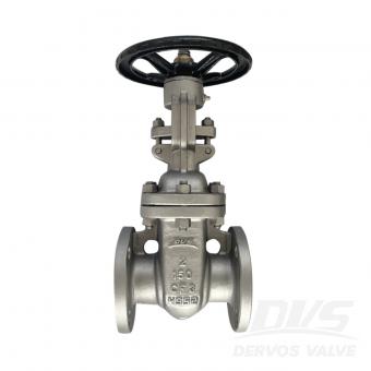
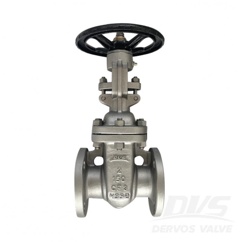
2" 150LB 게이트 밸브는 API에 따라 제작됩니다. 600 표준. 밸브 본체는 A351 CF3으로 만들어졌습니다. 그것은 구조적 볼트 커버, 라이징 스템 브라켓의 특징. 연결 모드는 RF입니다. 그리고 핸드휠 작동 모드가 있습니다.
지불:
30% when order confirmed, 70% before shipment제품 원산지:
China색:
Customization배송 포트:
Shanghai, China리드 타임:
30~60 days Ex Works after order confirmationMaterial:
A351 CF3Method of Operation:
Handwheel제품 설명
|
유형 |
문 판막 |
|
크기 |
2" |
|
압력 |
150LB |
|
연결 |
RF |
|
작업 |
핸드휠 |
|
몸 재료 |
A351 CF3 |
|
설계 표준 |
API 600 |
|
얼굴 면차원으로 |
ASME B16.10 |
|
끝 연결 |
ASME B16.5 RF |
|
시험 및 검사 코드 |
API 598 |
|
온도 |
-29 ~ 425°C |
|
해당되는 중간 |
물, 석유 및 가스 |
특징
1. 조밀한 구조, 간단한 구조, 조밀한 외관, 쉬운 조립 및 안정적인 작동;
2. 유연한 스위치, 쉬운 열고 닫는 작업.
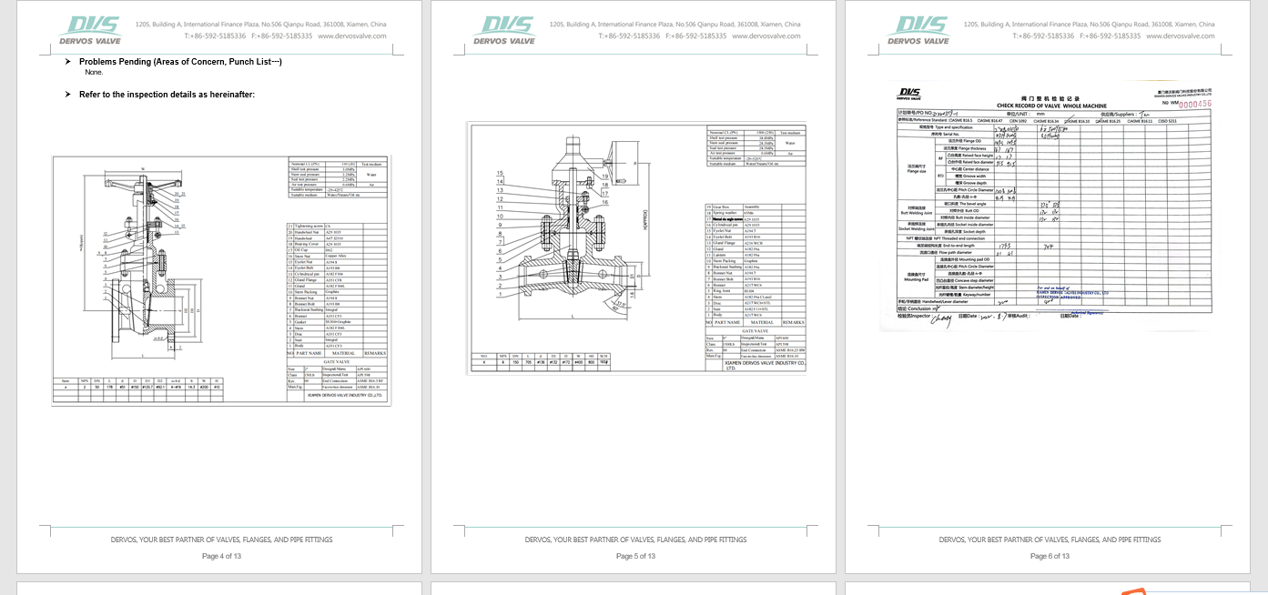
기술도면
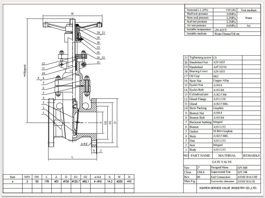
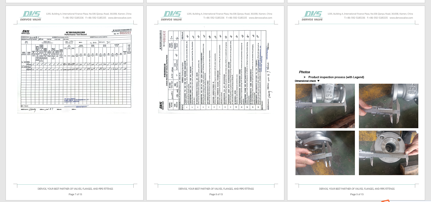
치수 확인

압력 테스트
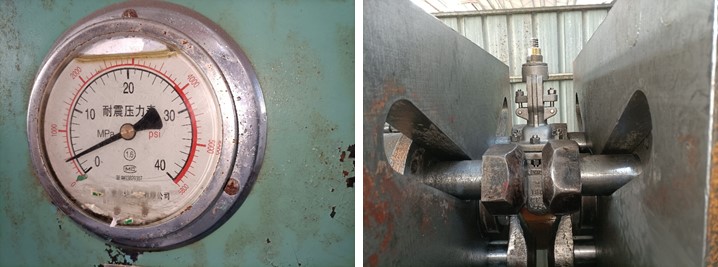
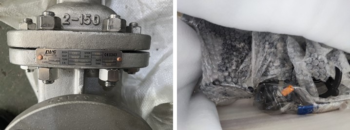
명판 및 포장
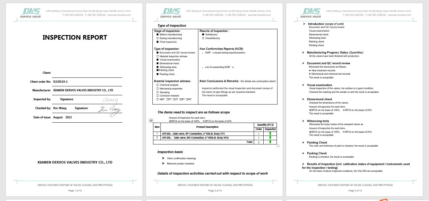
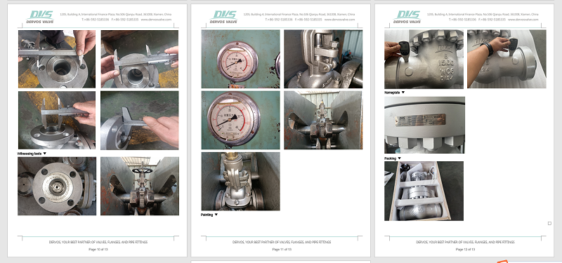
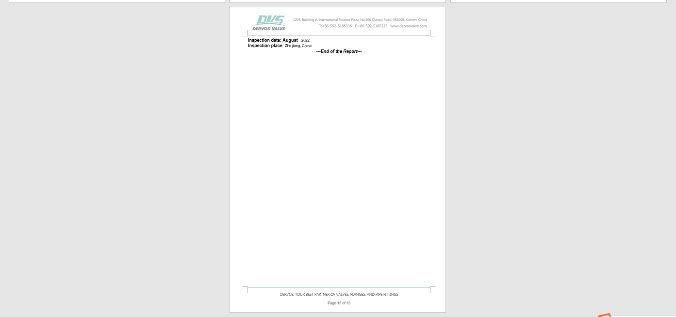
검사보고서
에 관심이 있다면 우리의 제품과한 자세한 내용을 알고 싶다면,메시지를 남겨주십시오 여기,우리가 응답할 것입니다 당신은 빨리 우리가 할 수 있습니다.
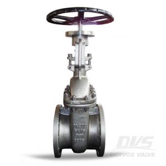
스테인레스 스틸 CF8M 게이트 밸브는 DIN 3352에 따른 플랜지 연결 및 핸드휠 작동으로 설계되었습니다. PN16 DN200 풀 포트 게이트 밸브는 OS&Y 구조, 탄력 있는 웨지 및 교체 가능한 시트를 갖추고 있습니다. 설계사양 설계 및 제조: DIN 3352 종단 간 차원: DIN3202 플랜지 끝: EN1092-1 테스트 및 검사: EN12266-1/2 디자인특징 -풀 보어 디자인 -우수한 유량 및 작은 마찰 손실 -밸브 개폐 토크 값이 낮음 -더 나은 착석감과 간편한 작동을 위한 유연한 웨지 -매끄러운 마감과 시트면의 우수한 밀봉성 - 모든 밸브는 추적성을 위해 몸체에 특정 번호로 제조됩니다. 빠른 세부정보 유형 문 판막 크기 DN 200 압력 PN 16 건설 볼트로 고정됨 보닛, 라이징 스템, 외부 나사 및 요크 연결 플랜지 연결 작업 핸드휠 본체 재질 스테인레스 스틸 CF8M 재료 다듬기 스테인레스 스틸 온도 범위 -268…~+648… 중간 물, 석유 및 가스 기원 중국 더보스 포장 포장은 결코 무시할 수 없는 중요한 부분입니다. Dervos는 주문의 안전하고 명확한 배송을 보장하기 위해 각 주문에 대한 포장 프로세스를 갖추고 있습니다.
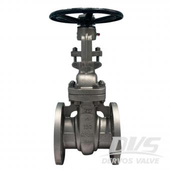
4" 150LB 게이트 밸브는 API에 따라 제작됩니다. 603 표준. 밸브 본체는 ASTM A351 CF8M+STL로 만들어졌습니다. 그것은 볼트 커버, 탄성 쐐기 및 라이징 스템의 구조적 특성. 그것은 테스트 및 검사는 API 598을 준수하며, 작동 모드는 핸드휠 작동입니다.
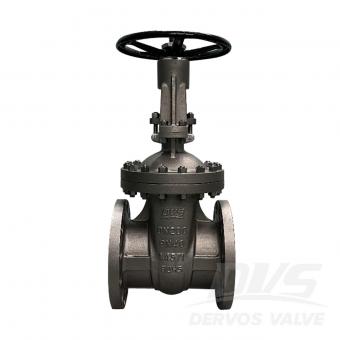
DN200 PN40 게이트 밸브는 EN1984에 따라 제작되었습니다. 기준. 밸브 몸체는 1.4571+STL로 제작되었습니다. 그것은 구조적 볼트 커버, 탄성 게이트, 라이징 스템 및 브라켓의 특징. 그것의 연결 모드는 EN1092-1/B입니다. 그리고 핸드 휠 작동 모드가 있습니다.
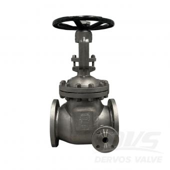
DN125 PN16 게이트 밸브는 DIN에 따라 제작됩니다. 3352 표준. 밸브 몸체는 1.4408로 만들어졌습니다. 그것은 구조적 SS316을 사용한 볼트 커버, 라이징 스템, 탄성 웨지의 특성 절연 재킷 및 구조 길이 325mm. 연결 모드는 RF입니다. EN1092-1 B1. 그리고 핸드 휠 작동 모드가 있습니다.
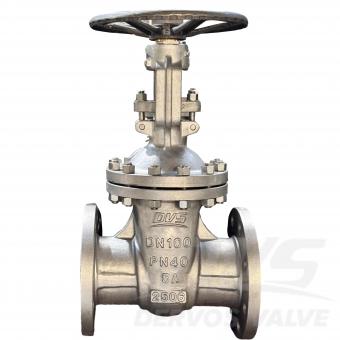
DN100 PN40 5A 듀플렉스 스테인리스 스틸 게이트 밸브는 EN 1984 표준에 따라 제작되었습니다. 밸브 본체는 ASTM A995 5A+STL 규격으로 제작되었습니다. 풀 보어(Full Bore), 볼트 체결 보닛, 요크가 있는 라이징 스템(Rising Stem), 플렉시블 웨지(Flexible Wedge) 구조의 특징을 가지고 있습니다. 연결 방식은 EN1092-1 B1이며, 핸드 휠 작동 방식을 채택했습니다.
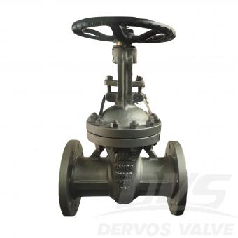
DN100 PN40 스테인리스 스틸 게이트 밸브는 EN 1984 표준에 따라 제작되었습니다. 밸브 본체는 X6CrNiMoTi17-12-2 재질로 만들어졌습니다. EN 1.4571(AISI 316Ti)은 입계 부식 및 중간 정도의 염화물 부식에 대한 저항성이 요구되는 중온 및 고온 환경, 특히 용접 후 열처리가 없는 용접 시스템에 널리 사용됩니다. 연결 방식은 EN558이며, 핸드휠이 장착되어 있습니다. operation mode. Product Parameters Type Stainless Steel Gate Valve Size DN100 Pressure PN40 Connection EN 558 Operation Hand Wheel Body Material X6CrNiMoTi17-12-2 Design Norm EN 1984 Face to Face dimension EN 1092 End connection EN 558 Test & Inspection Code EN 12266-1,2 Temperature -29 ~ 425°C Applicable Medium Water, Oil and Gas Features 1.Made from EN 1.4571 stainless steel, offering excellent corrosion resistance and high-temperature stability for PN40 pressure applications. 2.Gate valve design compliant with EN 1984 ensures reliable shutoff and long service life in industrial piping systems. Technical Drawing Dimension Checking Pressure Testing Spectrum Nameplate & Packing
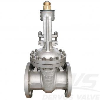
DN150 PN40 스테인리스 스틸 게이트 밸브는 EN 1984 표준에 따라 제작되었습니다. 밸브 본체는 X6CrNiMoTi17-12-2 재질로 만들어졌습니다. EN 1.4571(AISI 316Ti)은 입계 부식 및 중간 정도의 염화물 부식에 대한 저항성이 요구되는 중온 및 고온 환경, 특히 용접 후 열처리가 없는 용접 시스템에 널리 사용됩니다. 연결 방식은 EN558이며, 핸드휠이 장착되어 있습니다. operation mode. Product Parameters Type Stainless Steel Gate Valve Size DN150 Pressure PN40 Connection EN 558 Operation Hand Wheel Body Material X6CrNiMoTi17-12-2 Design Norm EN 1984 Face to Face dimension EN 1092 End connection EN 558 Test & Inspection Code EN 12266-1,2 Temperature -29 ~ 425 °C Applicable Medium Water, Oil and Gas Features 1.EN 1.4571 stainless steel construction provides strong resistance to pitting and stress corrosion in aggressive media. 2.DN150 PN40 configuration designed to EN 1984 standard ensures stable operation and tight isolation in medium-pressure pipelines. Technical Drawing Dimension Checking Pressure Testing Spectrum Nameplate & Packing
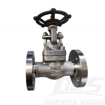
DN25 PN40 플랜지 게이트 밸브는 API602 표준에 따라 제작되었습니다. 밸브 본체는 A182-F316Ti 재질이며, 연결 방식은 EN1092-1 B1입니다. 또한 핸드휠이 장착되어 있습니다. 작동 모드. 제품 매개변수 유형 스테인리스 스틸 게이트 밸브 크기 디나25 압력 PN40 연결 EN1092-1 B1 작업 핸드휠 본체 재질 A182-F316Ti 디자인 표준 API 602 플랜지 치수 EN 1092 재질 적합 AISI/ASTM 시험 및 검사 규정 EN 12266 온도 -29 ~ 120 °C 적용 가능한 매체 물, 석유 및 가스 특징 1. F316Ti 스테인리스강 본체는 입자간 부식 및 고온 환경에 대한 저항성을 향상시킵니다. 2. API 602 규격에 따라 설계된 DN25 PN40 게이트 밸브와 EN1092-1 B1 플랜지는 공정 파이프라인에서 안정적인 작동과 완벽한 차단을 보장합니다. 기술 도면 치수 검사 압력 테스트 스펙트럼 검사 보고서
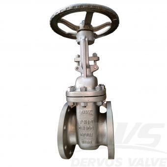
DN100 PN16 스테인리스 스틸 게이트 밸브는 DIN 3352 표준에 따라 제작되었습니다. 밸브 본체는 A351 CF8M+STL 재질이며, 볼트식 보닛, 라이징 스템, 플렉시블 웨지 등의 구조적 특징을 가지고 있으며, 면간 거리는 DIN 3202-F4 규격을 준수합니다. 연결 방식은 RF 방식이며, 핸들이 포함되어 있습니다. 작동 모드. 제품 매개변수 유형 스테인리스 스틸 게이트 밸브 크기 디나100 압력 PN16 연결 RF 작업 핸들 본체 재질 A351 CF8M+STL 디자인 표준 DIN 3350 대면 소음 3202-F4 플랜지 치수 EN 1092-1 시험 및 검사 규정 EN 12266 온도 - 29 ~ 425 °C 적용 가능한 매체 물, 석유 및 가스 특징 1. 상승형 스템 스테인리스 스틸 게이트 밸브 설계로 정밀한 유량 제어와 완벽한 차단 기능을 보장합니다. 2. PN16 등급에 RF 플랜지가 장착되어 있으며 DIN 3352 규격을 준수하고, 손잡이로 조작하여 손쉽게 제어할 수 있습니다. 기술 도면 치수 검사 압력 테스트 그림 명판 및 포장 검사 보고서
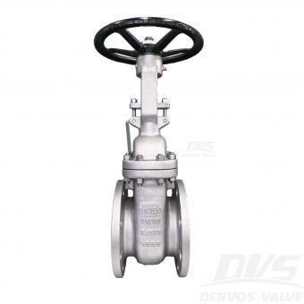
DN150 PN10 스테인리스 스틸 게이트 밸브는 EN 1984 표준에 따라 제작되었습니다. 밸브 본체는 1.4571 재질로 만들어졌습니다. 볼티드 본넷, 상승 스템, 플렉시블 웨지의 구조적 특성을 가지고 있습니다. 연결 방식은 EN 1092-1입니다. 그리고 핸드휠을 가지고 있습니다.작동 모드. 제품 매개변수 유형 스테인리스 스틸 게이트 밸브 크기 DN150 압력 PN10 연결 EN 1092-1 작동 핸드휠 본체 재질 1.4571+STL 설계 규격 EN 1984 면간 거리 DIN 3202-F4 플랜지 치수 EN 1092-1 D 테스트 및 검사 규격 EN 12266 온도 -46 ~ 200°C 적용 유체 물, 오일 및 스팀 특징 1. 스테인리스 스틸 1.4571 구조는 까다로운 산업용 애플리케이션에 뛰어난 내식성을 제공합니다. 2. 게이트 밸브 설계는 안정적인 차단 서비스를 위한 EN 1984 요구 사항을 준수합니다. 치수 검사 압력 테스트 명판 및 포장