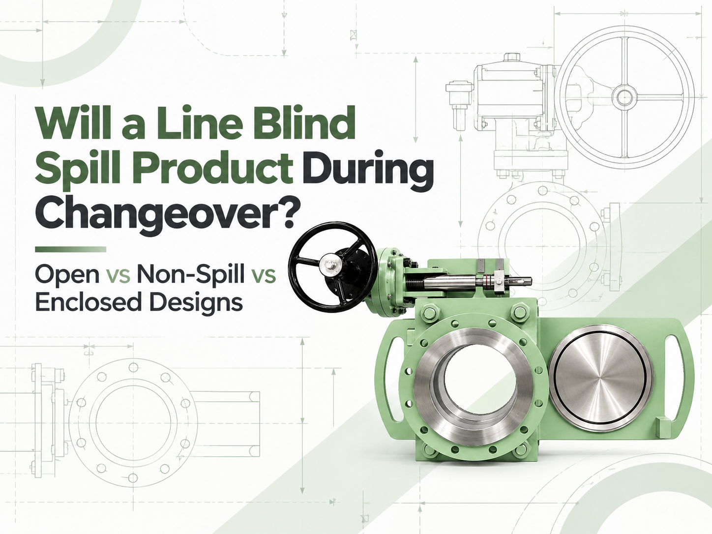
Yes, an open-body line blind can release residual product when it changes between the open and blind positions. A non-spill design does not make that residue disappear; it catches the liquid in a partial enclosure and directs it to a drain. An enclosed design can provide better control of liquid and vapour, but only when its housing, drain, vent and purge connections are engineered for the service. None of these labels should be read as permission to move the blind under live line pressure. Why Product Can Escape During Changeover When a line blind is fully clamped, its seals contain the process and the solid plate provides positive isolation in the blind position. Changeover is different. The sealing faces must separate before the spectacle or sliding plate can move. During that interval, the body cavity and plate path may be open to the surrounding area. The line should already be isolated, depressurised and drained, but “drained” rarely means perfectly dry. Liquid can remain as a film on the plate, collect in the lower body, or sit in a poorly drained pipe pocket. Gas service may leave flammable, toxic or odorous vapour. The amount released therefore depends as much on piping layout and the shutdown procedure as on the line blind itself. The Three Designs Manage Residue Differently Open-body design Residual liquid can drip from the exposed plate path into a temporary tray or the work area, while vapour disperses locally. This arrangement can suit water, steam condensate or other manageable media where easy access and visual inspection matter. It presents the highest potential for floor contamination and operator exposure. Non-spill design A bottom-and-side cover catches drips and sends them to a drain or recovery container; the top may remain open. This design is commonly considered for fuel terminals, marine service and liquid duties where ground or deck contamination must be controlled. It reduces dripping but may not contain vapour, and a blocked drain defeats its purpose. Enclosed design A housing surrounds more or all of the plate travel and may connect to a closed drain, purge, vent, flare or vapour-recovery system. It is better suited to toxic, flammable, odorous or environmentally sensitive service requiring controlled containment. The tradeoff is greater complexity in purging, inspection and maintenance, together with the need to manage trapped pressure deliberately. These names are not perfectly standardised across manufacturers. One supplier's “non-spill” model may be open at the top, while another product described as enclosed may use a more complete casing. The RFQ should show the enclosure arrangement and identify every opening rather than relying on the product name. Non-Spill Does Not Automatically Mean Zero Release For a liquid with low volatility, catching the remaining drops and routing them into a closed contai...
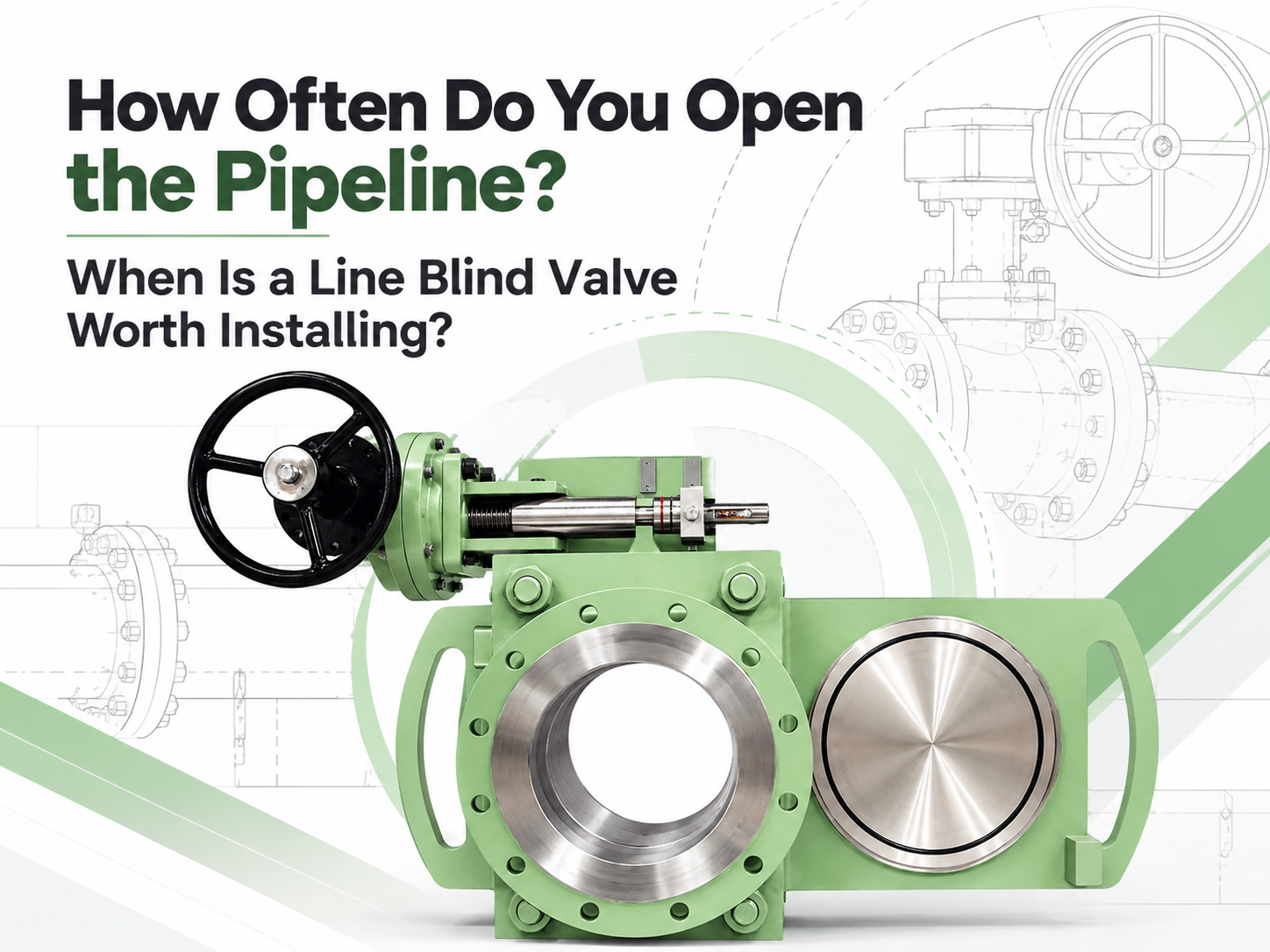
라인 블라인드 밸브는 파이프라인을 연간 여러 번 차단해야 하거나, 기존의 전환 작업으로 인해 수 시간의 가동 중단, 인양 작업 또는 유해 잔류물에 대한 상당한 노출이 발생하는 경우 평가해 볼 가치가 있습니다. 투자 회수를 보장하는 만능 작동 횟수 기준은 없습니다. 연간 두 번 작동하는 대형 중요 라인은 투자가 정당화될 수 있는 반면, 월 단위로 작동하는 소형의 접근이 쉬운 라인은 그렇지 않을 수 있습니다. 이 결정은 빈도만이 아니라 각 완전 격리 이벤트의 비용과 리스크를 기반으로 이루어져야 합니다. ‘연간 2회 작동’이라는 표준 규칙은 없습니다 일부 공급업체는 연간 1~2회의 전환을 스크리닝 임계값으로 사용합니다. 이는 논의의 시작점이 될 수는 있지만 엔지니어링 규칙은 아닙니다. 빈도는 DN50 유틸리티 라인과 DN600 공정 가스 메인 라인에서 매우 다른 결과를 가져옵니다. 사전 검토를 위해 다음 대역은 필수가 아니지만 유용합니다: 차단 빈도 초기 해석 주요 정비(턴어라운드)당 1회 이하 분리형 블라인드 또는 스펙터클 블라인드가 경제적인 경우가 많습니다. 연간 1~3회 인건비, 인양, 중단 시간 및 매체 리스크를 신중하게 비교하십시오. 분기별 내지 월별 A 퀵액션 라인 블라인드(은)는 일반적으로 강력한 후보입니다. 주간 또는 더 빈번함 목적에 맞게 제작되거나 자동화된 격리는 상세한 검토가 필요하며, 라인 블라인드가 요구되는 사이클 작업에 적합한지 확인해야 합니다. 모든 작업에 비계, 크레인, 여러 명의 배관공 또는 오랜 생산 중단이 필요한 경우, 낮은 작동 빈도에서도 설치를 뒷받침할 수 있습니다. 반대로, 공정이 압력, 온도, 재질 또는 유지보수 요구 사항을 수용할 수 없는 경우 잦은 작동이라도 라인 블라인드를 정당화하지 못합니다. 완전한 전환 작업 횟수 산정 전통적인 블라인딩 작업은 단순히 판을 이동하는 것 이상입니다. 라인이 안전해진 후 작업자들은 볼트를 풀고, 플랜지 조인트를 벌리고, 블라인드 또는 스페이서를 다루고, 개스킷을 교체하고, 정렬을 복원하고, 조인트를 조이고 누출 점검을 완료합니다. 대형 규격의 경우 리깅 및 접근 장비가 추가됩니다. 퀵액션 라인 블라인드는 설치된 어셈블리 내부에 스펙터클 또는 슬라이딩 플레이트가 지지된 상태를 유지합니다. 제조업체 문헌에 따르면 기존 플랜지 작업에 필요한 맨아워(man-hour) 대신 몇 분 만에 1명이 전환 작업을 수행할 수 있다고 흔히 보고됩니다. 이러한 수치는 스크리닝에 유용하지만, 프로젝트 계산에는 플랜트 자체의 절차
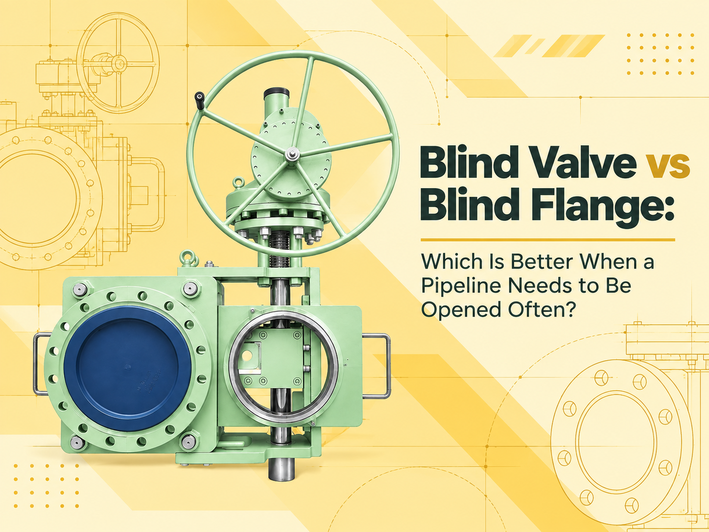
파이프라인을 자주 개방하고 확실하게 차단해야 하는 경우, 라인 블라인드 밸브가 일반적으로 더 나은 선택입니다. 이 밸브는 블라인드 메커니즘을 영구적으로 설치된 상태로 유지하며, 작업자가 볼트로 고정된 끝단 마개를 반복적으로 제거할 필요 없이 개방 위치와 차단 위치를 전환할 수 있게 해줍니다. 블라인드 플랜지는 비용이 저렴하고 움직이는 부품이 적지만, 장기간 닫힌 상태로 유지될 파이프 끝을 막는 데 더 적합합니다. 이 답변은 “블라인드 플랜지”가 파이프나 노즐 끝에 볼트로 고정된 단단한 플랜지를 의미한다고 가정합니다. 두 플랜지 사이에 설치되는 스펙터클 블라인드나 탈착식 스페이드는 유사한 고체 금속 차단 장벽을 형성하지만, 이는 다른 장치입니다. 잦은 개방은 비용 계산을 변화시킵니다 구매 가격 면에서는 블라인드 플랜지가 유리합니다. 구조가 단순하고 유지보수는 주로 플랜지 면, 개스킷, 스터드 및 너트를 점검하는 것으로 제한됩니다. 가끔 있는 정기 보수 기간에만 마개를 제거한다면, 이러한 단순함을 능가하기는 어렵습니다. 반복적인 개방은 상황을 바꿉니다. 블라인드 플랜지를 제거하려면 라인을 차단하고, 압력을 낮추고, 배수 또는 퍼지 작업을 수행한 뒤 안전을 확인해야 합니다. 그런 다음 볼트를 풀고, 플랜지를 지지하고, 밀봉 면을 분리해야 합니다. 더 큰 플랜지의 경우 리프팅 장비가 필요할 수 있습니다. 재조립 시에는 새 개스킷을 사용하고, 볼트를 제어된 방식으로 조이며, 누출 테스트를 수행해야 합니다. 이러한 단계 중 특별한 것은 없지만, 이를 반복하면 저비용 부품이 노동 집약적인 운영 방식으로 변하게 됩니다. 라인 블라인드 밸브 역시 승인된 설계 및 운영 절차에 별도의 명시가 없는 한, 위치를 변경하기 전에 라인을 차단하고 압력을 낮춰야 합니다. 이 밸브의 장점은 기계적 취급에 있습니다. 플레이트, 스페이서 또는 슬라이딩 요소가 본체 내에 고정되어 있으며, 메커니즘이 밀봉 면을 분리, 이동 및 재고정합니다. 수동 기어는 적절한 작동 힘에 적합할 수 있으며, 대형 사이즈나 원격 작동의 경우 전기, 공압 또는 유압 구동 방식이 정당화될 수 있습니다. 블라인드 밸브는 취급을 줄여주지만 유지보수할 장비를 추가합니다 잦은 전환의 경우, 블라인드 밸브는 작업을 단축하고 무거운 플레이트, 볼트 및 개스킷의 반복적인 취급을 줄일 수 있습니다. 개방 또는 폐쇄 위치는 일반적으로 외부 플레이트나 위치 표시기를 통해 확인할 수 있어 현장 검증에 도움이 됩니다. 또í•
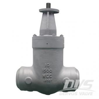
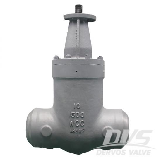
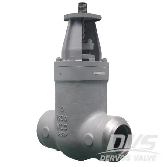
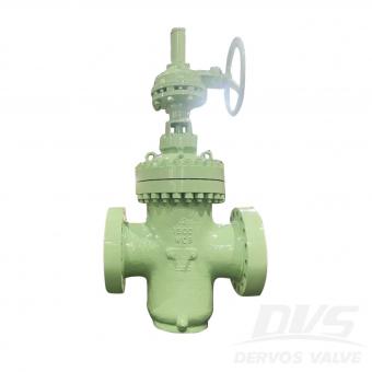
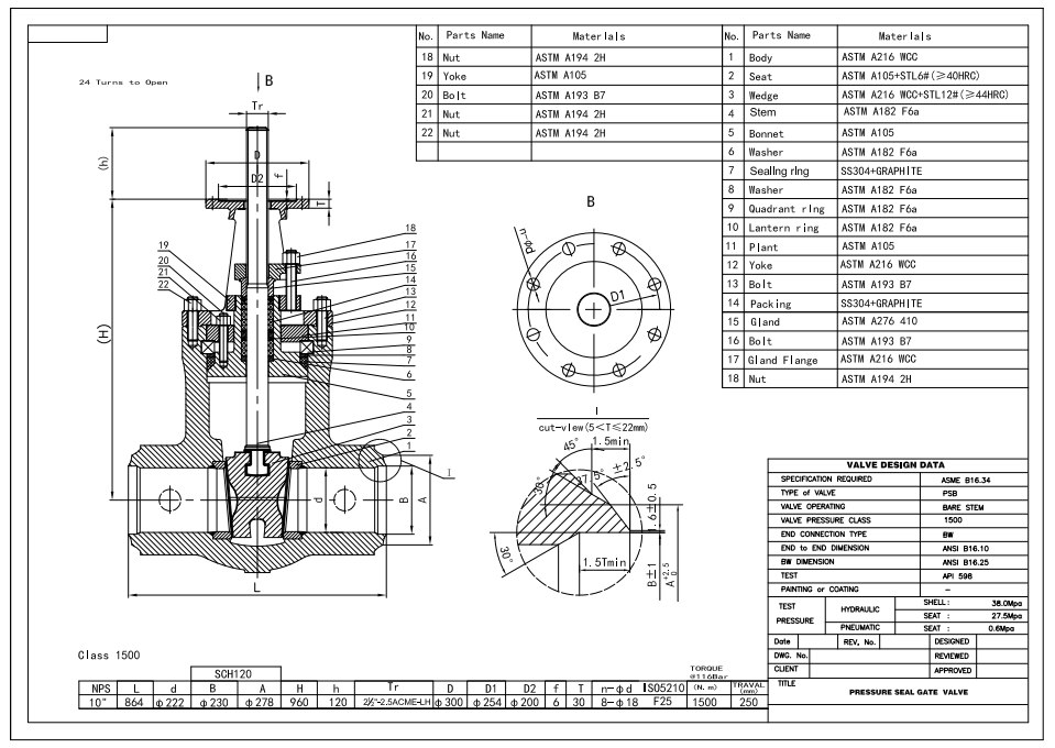
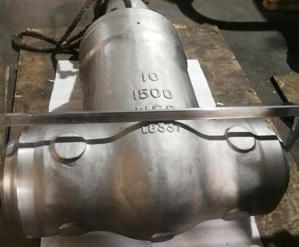
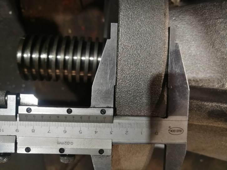
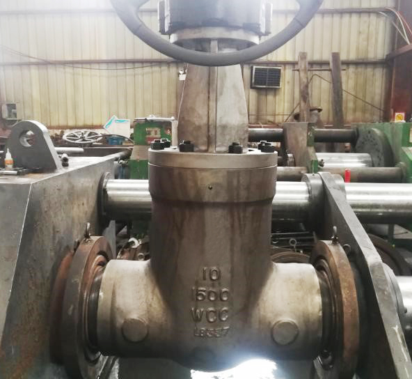
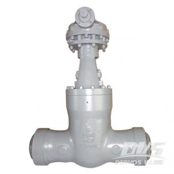
10'' 1500LB 게이트 밸브는 ASME B16.34 표준에 따라 만들어집니다. 밸브 본체는 WCC로 제작되었습니다. 그것은 압력 자체 밀봉, 상승 줄기, 탄성 쐐기 및 864mm의 구조적 길이의 구조적 특성을 가지고 있습니다. 밸브 스템의 양쪽 끝은 나사산이 있습니다. BW 연결 유형이 있습니다.
지불:
30% when order confirmed, 70% before shipment제품 원산지:
China색:
Customization배송 포트:
Shanghai, China리드 타임:
30~60 days Ex Works after order confirmationMaterial:
ASTM A216 WCCMethod of Operation:
Bare Stem제품 설명
|
유형 |
게이트 밸브 |
|
크기 |
10'' |
|
압력 |
1500LB |
|
본체 재질 |
ASTM A216 WCC |
|
디자인 규범 |
ASME B16.34 |
|
밸브 유형 |
PSB |
|
밸브 작동 |
베어 스템 |
|
끝 연결 유형 |
흑백 |
|
엔드 투 엔드 차원 |
ANSI B16.10 |
|
흑백 차원 |
ANSI B16.25 |
|
테스트 |
API 598 |
|
적용 매체 |
물, 석유 및 가스 |
특징
1. 탄성 쐐기가 채택되어 고압 조건에서 특정 탄성 보상이 있으며 밀봉이 더 안정적입니다.
2. 씰링 구조와 씰링 재료는 다양한 작업 조건 및 예압 요구 사항에 따라 선택할 수 있습니다.
기술 도면
치수 검사
증인 시험
명판 및 포장
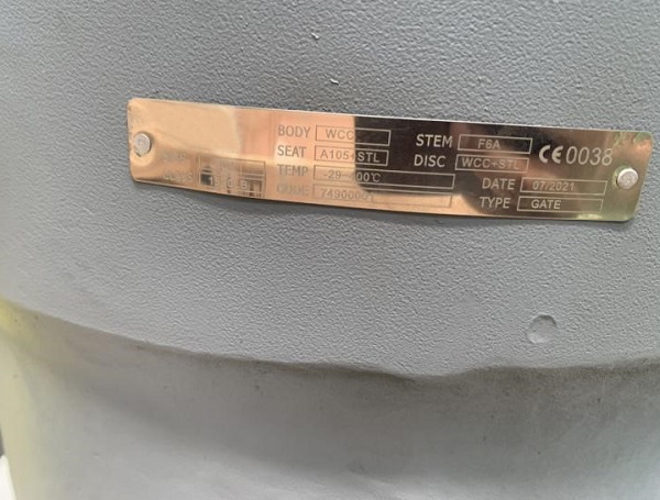
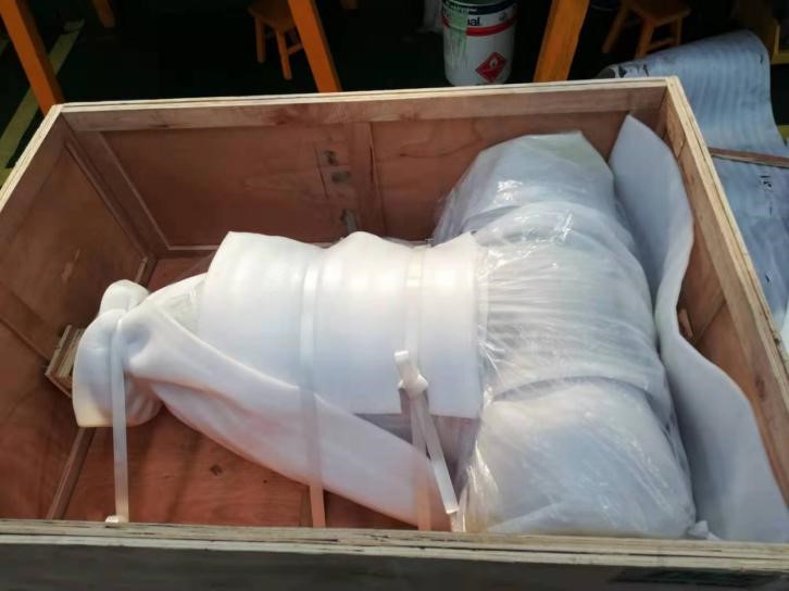
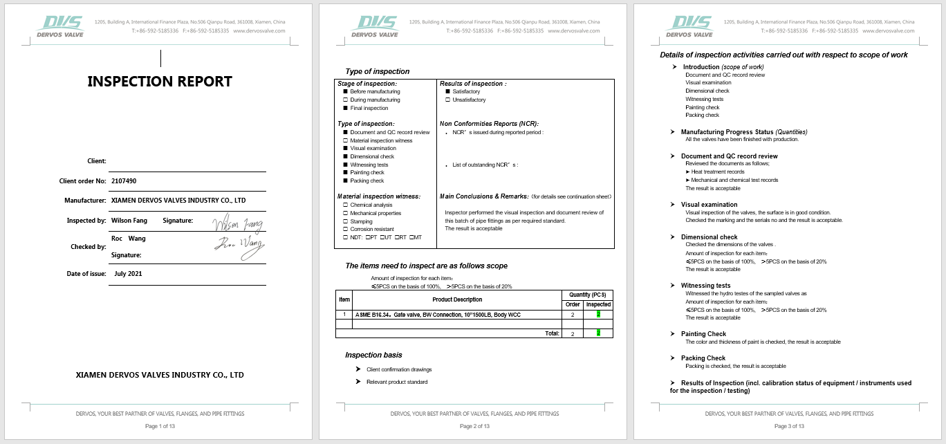
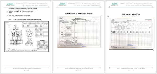
검사 보고서
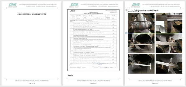
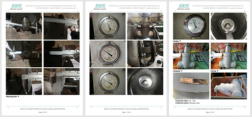
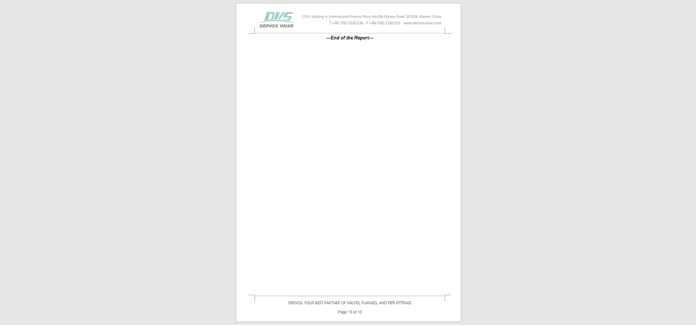
에 관심이 있다면 우리의 제품과한 자세한 내용을 알고 싶다면,메시지를 남겨주십시오 여기,우리가 응답할 것입니다 당신은 빨리 우리가 할 수 있습니다.
8 인치 클래스 2500 게이트 밸브는 압력 실 보닛, 맞대기 용접 연결 및 기어 박스 작동으로 설계되었습니다. 8 인치 게이트 밸브에는 탄소강 wcb 본체와 트림 5가 있습니다. 빠른 세부 사항 유형 문 판막 크기 8 인치 설계 압력 아니 2500 구성 압력 실링 보닛, 플렉시블 웨지, 금속-금속 시트 연결 타입 대상 용접 (sw) 작업 유형 변속 장치 조작 바디 재료 a217 화장실 트림 재료 트림 5 디자인 코드 API 600 대면 치수 저 같은 b16.10 연결 종료 저 같은 b16.25 압력 및 온도 저 같은 b16.34 매질 물, 석유와 가스 유래 중국 치수 & amp; 재료 nps dn 수업 2 2 1/2 삼 4 6 8 10 12 14 16 18 20 24 50 65 80 100 150 200 250 300 350 400 450 500 600 l (rf) 900 파운드 368 419 381 457 610 737 838 965 1029 1130 & emsp; & emsp; & emsp; 1500 파운드 368 419 470 546 705 832 991 1130 1257 1384 & emsp; & emsp; & emsp; 2500 파운드 451 508 578 673 917 1022 1270 & emsp; & emsp; & emsp; & emsp; & emsp; & emsp; l1 (bw) 900 파운드 216 254 305 355 508 660 787 914 991 1092 1346 1473 1600 년 1500 파운드 216 254 305 406 559 711 864 991 1067 1194 1697 & emsp; & emsp; 2500 파운드 279 330 368 457 610 762 914 1041 1118 1245 & emsp; & emsp; & emsp; l2 (rtj) 900 파운드 371 422 384 460 613 740 841 968 1038 1140 & emsp; & emsp; & emsp; 1500 파운드 371 422 473 549 711 841 1000 1146 1276 1407 & emsp; & emsp; & emsp; 2500 파운드 454 514 584 683 927 1038 1292 & emsp; & emsp; & emsp; & emsp; & emsp; & emsp; h (오픈) 900 파운드 554 637 680 796 1084 1372 1494 1550 1960 2210 & emsp; & emsp; & emsp; 1500 파운드 554 637 767 875 1094 1372 1655 1834 2150 2260 2460 2721 2940 2500 파운드 610 654 753 850 1254 1374 1685 1894 2226 2382 2585 & emsp; & emsp; 승 900 파운드 300 350 350 400 560 460 * 610 * 610 * 610 * 760 * & emsp; & emsp; & emsp; 1500 파운드 300 450 450 560 305 * 460 * 610 * 610 * 760 * 760 * & emsp; & emsp; & emsp; 2500 파운드 500 500 600 600 460 * 460 * 610 * & emsp; & emsp; & emsp; & emsp; & emsp; & emsp; 무게 (rf) 900 파운드 50 84 92 154 341 622 950 1295 1720 2380 & emsp; & emsp; & emsp; 1500 파운드 60 91 128 182 394 795 1370 2120 2800 3870 & emsp; & emsp; & emsp; 2500 파운드 121 175 195 229 720 1295 2250 & emsp; & emsp; & emsp; & emsp; & emsp; & emsp; 무게 (bw) 900 파운드 39 64 82 120 266 524 760 1090 1450 2018 년 & emsp; & emsp; & emsp; 1500 파운드 46 71 85 130 292 578 974 1615 2010 년 2815 3315 4150 5219 2500 파운드 88 135 144 158 500 892 1550 1978 2580 3780 5988 & emsp; & emsp; * 수동 기어 오퍼레이터 권장 아니. 부품 wcb 화장실 화장실 c5 cf8 cf8m 1 신체 a216 화장실 a217 화장실 a217 화장실 a217 c5 a351 cf8 a351 cf8m 2 좌석 a182 f6a a182 f22 a182 f22 a182 f5 a182 f304 a182 f316 삼 쐐기 a216 화장실 a217 화장실 a217 화장실 a217 c5 a351 cf8 a351 cf8m 4 줄기 a182 f6a saehnv3 a182 f304 a182 f316 5 스터핑 박스 a216 화장실 a217 화장실 a217 화장실 a217 c5 a351 cf8 a351 cf8m 6 씰링 아니 316l 유연한 흑연 +316 7 스플릿 링 강철 f6 f6 f6 a182 f304 f316 8 백 링 강철 강철 강철 강철 ss ss 9 볼트 a193 b7 a193 b7 a193 b7 a193 b7 a193 b8 a193 b8 10 너트 a194 2 시간 a194 2 시간 a194 2 시간 a194 2 시간 a194 gr.8 a194 gr.8 11 멍에 a216 화장실 a217 화장실 a217 화장실 a217 c5 a351 cf8 a351 cf8m 12 볼트 a193 b7 a193 b7 a193 b7 a193 b7 a193 b8 a193 b8 13 너트 a194 2 시간 a194 2 시간 a194 2 시간 a194 2 시간 a194 gr.8 a194 gr.8 14 포장 판 아니 410 아니 410 아니 410 아니 410 ANSI 304 아니 316 15 포장 유연한 흑연 그리고 반지) 또는 ptfe 16 분할 핀 강철 강철 강철 강철 강철 강철 17 아이 볼트 a193 b7 a193 b7 a193 b7 a193 b7 a193 b8 a193 b8 18 선 a182 f6 a182 f6 a182 f6 a182 f6 a182 f304 a182 f316 19 글 랜드 플랜지 a105 a105 a105 a105 a182 f304 a182 f316 20 너트 a194 2 시간 a194 2 시간 a194 2 시간 a194 2 시간 a194 gr.8 a194 gr.8 21 마개 a193 b7 a193 b7 a193 b7 a193 b7 a193 b7 a193 b7 22 줄기 너트 ni- 레지스트 a439-d2 23 기어 박스 구입 한 24 보호자 강철 25 명찰 ANSI 304 26 대갈못 ANSI 304
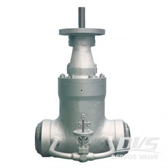
8" 1500LB 게이트 밸브는 ASME B16.34 표준.에 따라 만들어집니다. 밸브 본체는 WCC.로 만들어지며 압력 자체 밀봉, 탄성 게이트의 구조적 특성과 711mm의 구조적 길이를 가지고 있습니다. . 자체 밀봉 밸브의 작동 원리는 주로 쐐기 밀봉 표면을 사용하여 압력 하에서 밀봉하는 것입니다.
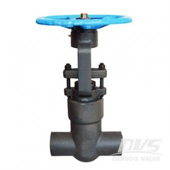
고압 클래스 4500 게이트 밸브는 CS A105,로 만들어진 PSB 및 SW 연결구.로 설계되었습니다. 2인치 게이트 밸브는 검사 표준 API 598 및 설계 표준 API 602.를 따릅니다. dervos는 고객에게 다양한 크기, 재질, 표준, 설계 압력, 구조, 작동 유형 및 연결 유형.의 밸브를 제공함으로써 맞춤형 서비스를 제공할 수 있습니다.
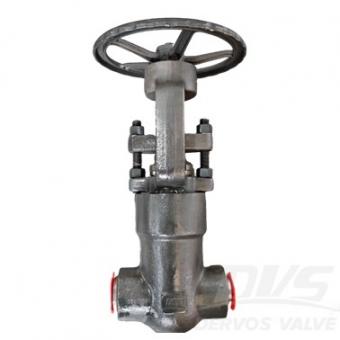
2인치 900LB 압력 씰 보닛 게이트 밸브는 ASME B16.34 표준에 따라 제작되었습니다. 밸브 본체는 A182-F91 재질로 제작되었습니다. PSB, OS&Y, 솔리드 웨지 구조의 특성을 가지고 있습니다. 연결 방식은 BW sch 80 ASME B16.25이며, 핸드휠 작동 모드를 갖추고 있습니다.
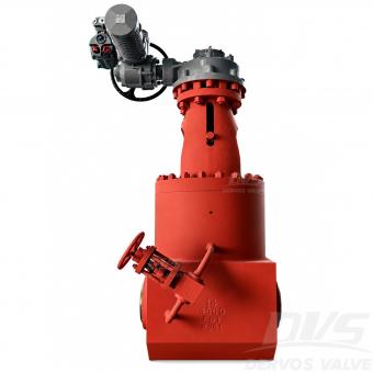
이 14인치 4500LB F91 압력 밀봉 게이트 밸브는 고온 및 고압 발전소 보일러 서비스용으로 설계되었습니다. ASTM A182 F91 Type 2 재질, 압력 밀봉 보닛, 병렬 이중 디스크 구조, BW 엔드, AOX 전동 액추에이터 및 압력 균등화를 위한 바이패스 밸브를 특징으로 합니다.
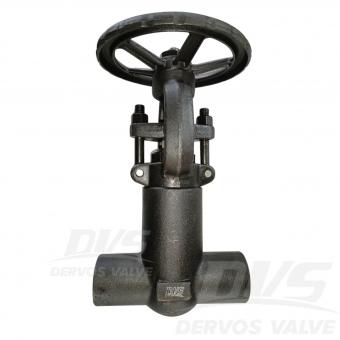
1/2" 1500LB 압력 씰 게이트 밸브는 BS3799 표준에 따라 제작되었습니다. 밸브 본체는 A105N으로 제작되었습니다. 압력 씰 구조 특성을 가지고 있습니다. 연결 방식은 FNPT입니다. 또한 핸드 휠 작동 방식을 갖추고 있습니다.작동 방식입니다. 제품 매개변수 유형 압력 씰 게이트 밸브 크기 1/2" 압력 1500LB 연결 FNPT 작동 핸드 휠 본체 재질 ASTM A105 설계 규격 ASME B16.3 면간 거리 제조업체의 나사식 끝단(NPT) 치수 ASME B1.20.1 시험 및 검사 코드 API 598 온도 -29 ~ 425°C 적용 매체 물, 오일 및 가스 특징 1. 압력 씰 보닛은 고압 Class 1500 서비스 요구 조건에서 향상된 밀봉 성능을 제공합니다. 2. A105N 단조강 본체와 1/2" FNPT 끝단은 높은 강도와 안전한 나사식 설치를 보장합니다. 기술 도면 치수 확인 압력 시험 명판 및 포장 검사 보고서