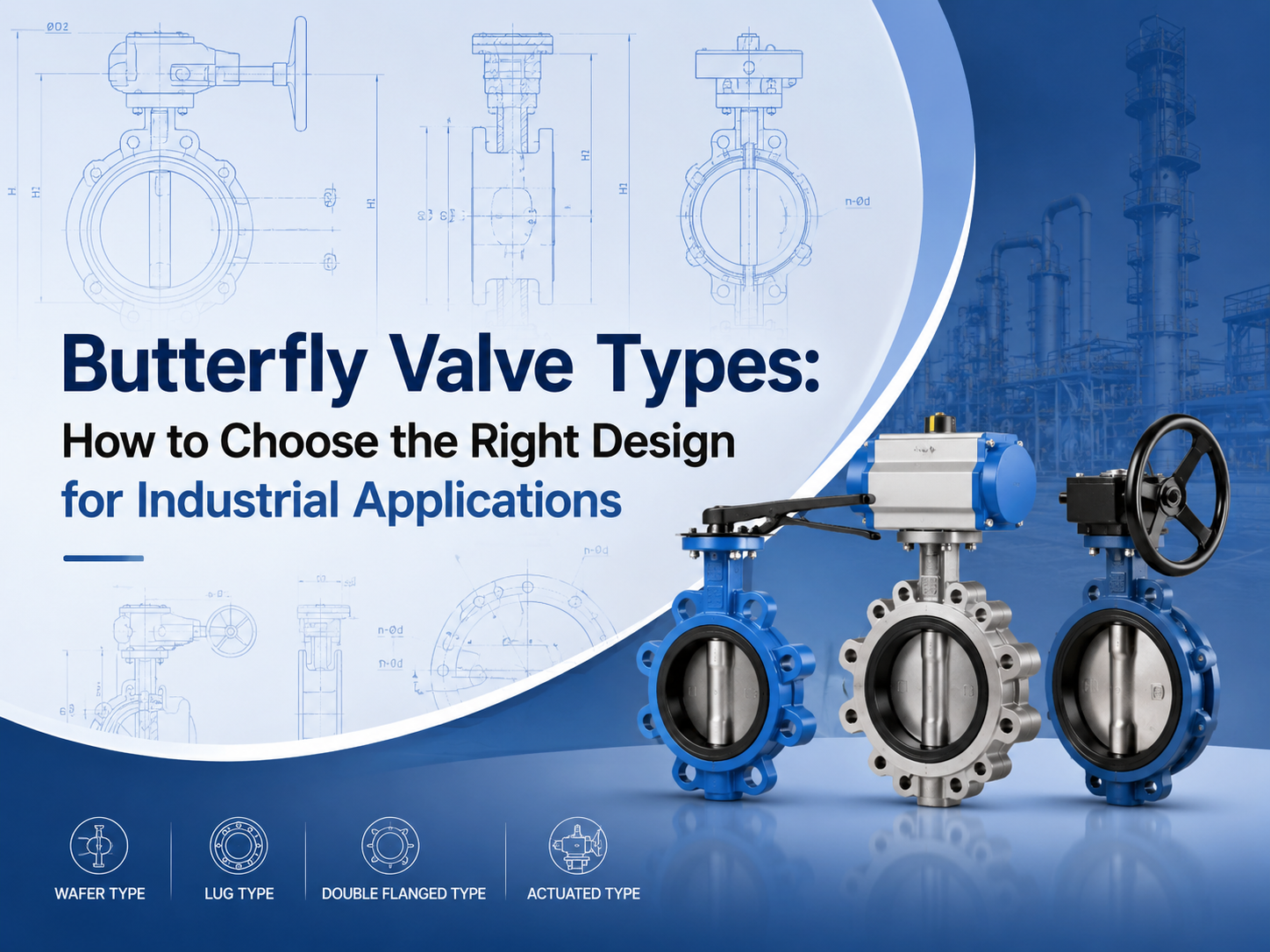
The main butterfly valve types include concentric, double offset, triple offset, wafer, lug, flanged, soft-seated, metal-seated, manual, pneumatic, and electric butterfly valves. The right choice depends on pressure, temperature, media, leakage requirement, installation space, and operation frequency. What Are the Main Butterfly Valve Types? Butterfly valves are usually classified by disc design, body connection, seat material, and actuation method. This classification is important because two valves may both be called butterfly valves, but their service limits can be very different. A butterfly valve uses a rotating disc to isolate or regulate flow. Because of its compact structure, light weight, and quarter-turn operation, it is widely used in water treatment, power plants, chemical processing, HVAC, marine systems, and general industrial pipelines. For buyers, the key question is not simply “which type is cheaper?” It is “which type can handle the actual pressure, temperature, media, and sealing requirement?” Concentric Butterfly Valve A concentric butterfly valve has the stem located on the centerline of the valve body and disc. It is also called a centerline butterfly valve. This type is commonly used for low-pressure and general-service applications, especially with water, air, and non-aggressive fluids. It is simple, economical, and easy to maintain. The limitation is seat wear. During opening and closing, the disc stays in contact with the soft seat for much of its movement. For higher pressure, higher temperature, or stricter shutoff requirements, double offset or triple offset designs are often more suitable. Double Offset Butterfly Valve A double offset butterfly valve uses two offsets to reduce friction between the disc and seat. This improves sealing performance and helps extend service life compared with a basic concentric design. Double offset butterfly valves are often selected for medium-pressure industrial service, including oil and gas, water supply, power generation, and chemical systems. They are useful when the application needs better durability but does not require a full metal-seated triple offset design. This type is also commonly called a high-performance butterfly valve. Before selection, buyers should confirm the pressure class, seat material, shaft sealing design, and expected operation frequency. Triple Offset Butterfly Valve A triple offset butterfly valve adds a third geometric offset to create a more advanced sealing structure. It is typically used for high-temperature, high-pressure, or severe-service applications. The design reduces rubbing between the sealing surfaces during operation. Many triple offset butterfly valves use metal seats, making them suitable for steam, oil and gas, chemical, and other demanding media. For these applications, standards and testing matter. Buyers often need t...
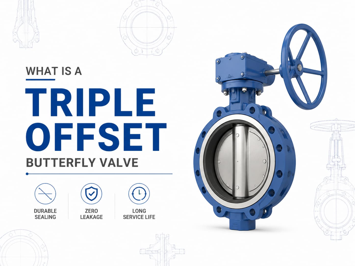
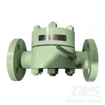
A 트리플 오프셋 버터플라이 밸브은 기존의 탄성 시트형 또는 더블 오프셋 버터플라이 밸브가 압력, 온도 또는 누설 요구사항을 충족하지 못하는 응용 분야를 위해 설계된 고성능 차단 밸브입니다. 3중 오프셋 밀봉 설계를 사용하여 작동 중 디스크와 시트 사이의 마찰을 줄인 금속 대 금속 밀봉 메커니즘을 구현하므로 오일 및 가스, 석유화학, 발전, LNG, 증기 및 산업 공정 시스템과 같은 까다로운 서비스에 적합합니다. 트리플 오프셋 버터플라이 밸브 설계 및 작동 원리 디스크와 시트의 중심선에 샤프트가 위치하는 동심형 버터플라이 밸브와 달리, 트리플 오프셋 버터플라이 밸브은 세 가지 독립적인 기하학적 오프셋을 적용합니다. 첫 번째 오프셋은 샤프트를 밸브 본체의 중심선에서 이동시키고, 두 번째 오프셋은 샤프트를 배관 중심선에서 이동시키며, 세 번째 오프셋은 원형 밀봉 형상 대신 원뿔형 밀봉 표면을 적용합니다. 이 형상은 회전이 시작된 직후 디스크가 시트에서 떨어져 이동하도록 하여 밀봉 표면 사이의 마찰을 제거합니다. 이 설계의 주요 장점은 밀봉력이 연질 재료의 지속적인 압축이 아니라 토크에 의해 생성된다는 점입니다. 고온 서비스가 필요한 경우, 엘라스토머 시트는 높은 온도에서 열화될 수 있으므로 금속 시트형 트리플 오프셋 버터플라이 밸브이 자주 선호됩니다. 매체에 마모성 입자 또는 부식성 화학물질이 포함된 경우, 장기간 작동 중 침식, 부식 및 누설을 방지하기 위해 디스크, 시트 및 본체의 재질 선택이 매우 중요합니다. 트리플 오프셋 버터플라이 밸브 표준 및 재질 트리플 오프셋 버터플라이 밸브는 일반적으로 API 609, EN 593 및 ISO 5752와 같은 표준에 따라 제조되며, 설계 요구사항에 따라 압력 등급은 Class 150부터 Class 600 이상까지 다양합니다. 일반적인 재질에는 탄소강, 스테인리스강, 듀플렉스 스테인리스강, 알루미늄 청동 및 니켈 기반 합금이 포함됩니다. 부식성 해수 응용 분야에서는 C95500 또는 C95800과 같은 알루미늄 청동 합금이 선택될 수 있으며, 사워 서비스 응용 분야에서는 NACE MR0175/ISO 15156 요구사항을 준수하는 재질이 필요할 수 있습니다. 트리플 오프셋 버터플라이 밸브 밀봉 성능 및 누설 제어 트리플 오프셋 버터플라이 밸브의 밀봉 성능은 밀봉 링, 시트 표면 마감, 작동 토크 및 재질 호환성 간의 상호작용에 따라 결정됩니다. 밀봉 표면은 최종 폐쇄 위치에서만 접촉하므로 기존 버터플라이 밸브 설계와 비교하여 기계적 마모가 크게 감소합니다. 중요한 차단 작업에서 제로 누설이
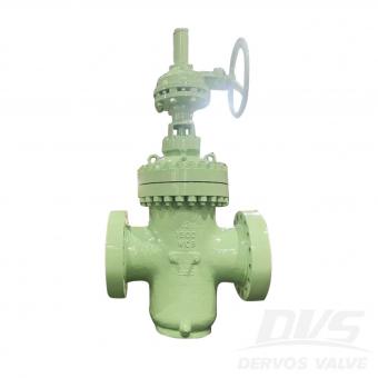
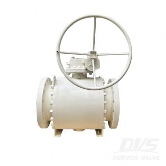
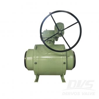
볼 밸브와 플러그 밸브는 모두 산업용 배관 시스템에서 개폐 제어 및 차단에 사용되는 90도 회전식 밸브입니다. 두 밸브는 유사한 작동 원리를 공유하지만, 내부 설계 차이로 인해 특히 밀봉 성능, 압력 허용 능력, 작동 토크, 유지보수 요구 사항 및 다양한 유체에 대한 적합성 측면에서 서로 다른 성능 특성을 보입니다. 볼 밸브와 플러그 밸브 중 선택은 밸브 유형에 대한 선호보다 실제 운전 조건을 기준으로 해야 합니다. 적용 분야에서 긴밀한 차단, 빈번한 작동, 낮은 작동 토크가 필요하다면 볼 밸브가 흔히 선호됩니다. 시스템에 오염된 유체, 마모성 입자 또는 큰 유로가 포함되는 경우 플러그 밸브가 더 높은 신뢰성을 제공할 수 있습니다. 설계 차이와 밀봉 성능 은볼 밸브는 관통 구멍이 뚫린 구형 차단 요소를 사용합니다. 밸브가 열리면 관통 구멍이 배관과 정렬되어 거의 제한 없는 유로를 제공합니다. 90도 회전하면 볼의 막힌 부분이 통로를 차단하여 차단 기능을 수행합니다. 플러그 밸브는 중앙을 관통하는 유로가 있는 원통형 또는 원추형 플러그를 사용합니다. 플러그는 본체 내부에서 회전하여 유량을 제어합니다. 설계에 따라 플러그 밸브는 윤활식, 슬리브식 또는 비윤활식으로 제작될 수 있으며, 각 구조는 서로 다른 밀봉 특성을 제공합니다. 밀봉 메커니즘은 두 밸브의 주요 차이점 중 하나입니다. 볼 밸브는 일반적으로 소프트 시트, 금속 시트 또는 두 가지를 조합한 방식을 사용하여 신뢰성 있는 차단을 달성합니다. 시스템에서 특히 가스 서비스나 중요 공정 적용 분야와 같이 기포 누설 없는 차단이 필요한 경우, 적절히 선정된 볼 밸브는 우수한 밀봉 성능을 제공할 수 있습니다. 플러그 밸브는 플러그와 밸브 본체 또는 슬리브 사이의 접촉에 의존합니다. 윤활식 플러그 밸브는 플러그와 본체 사이에 주입된 실란트를 사용하여 마찰을 줄이고 밀봉 성능을 향상시킵니다. 이 설계는 실란트가 밀봉 표면을 보호하는 데 도움을 주기 때문에 유체에 오염물이 포함된 적용 분야에서 우수한 성능을 발휘할 수 있습니다. 적용 시 고려 사항 운전 조건은 볼 밸브 또는플러그 밸브중 어느 것이 더 적합한지를 결정합니다. 볼 밸브는 신뢰성 있는 차단이 필요한 석유 및 가스, 석유화학, LNG, 화학 처리 및 발전 산업에서 널리 사용됩니다. 플로팅 볼 밸브는 일반적으로 낮은 압력 시스템에 적용되며, 트러니언 장착 볼 밸브는 트러니언 지지가 작동 토크를 줄여주기 때문에 대구경 및 높은 압력 등급에서 선호됩니다. 밸브가 빈�

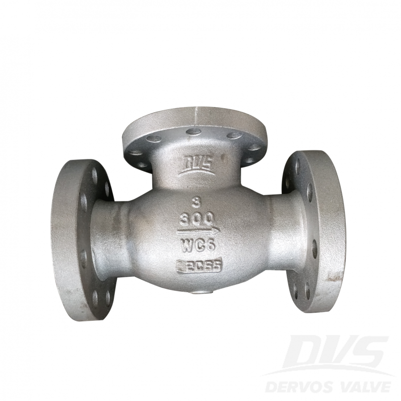
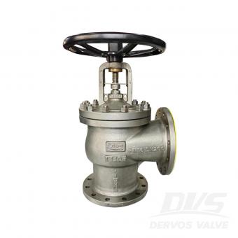
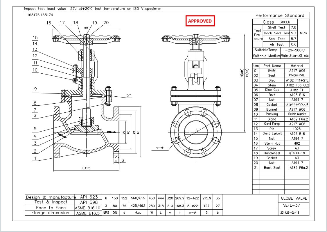
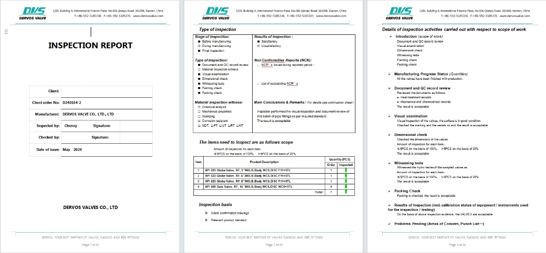
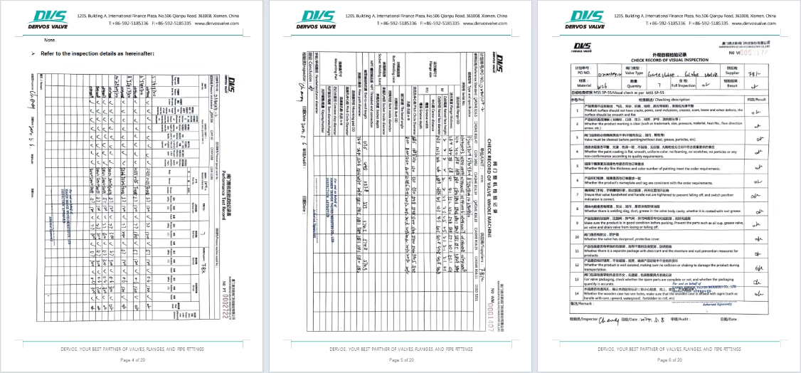
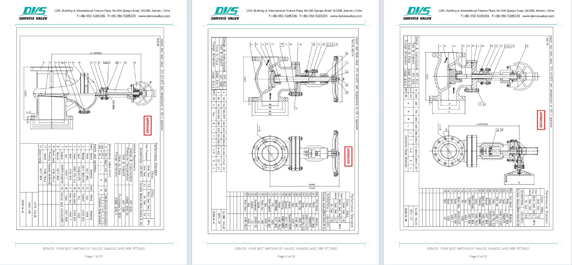
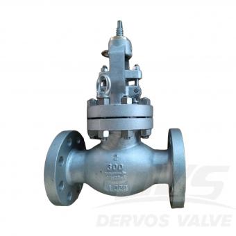
3인치 300LB 합금강 글로브 밸브는 API623 표준에 따라 제작됩니다. 밸브 본체는 A217 WC6 재질로 제작되었으며, 관통형 구조와 317.5mm의 길이를 가지고 있습니다. 연결 방식은 RF이며, 핸드휠 작동 방식을 사용합니다.
지불:
30% when order confirmed, 70% before shipment제품 원산지:
China색:
Customization배송 포트:
Shanghai, China리드 타임:
30~60 days Ex Works after order confirmationMaterial:
A216 WC6Method of Operation:
H.W.|
유형 |
합금강 글로브 밸브 |
|
크기 |
3인치 |
|
압력 |
300파운드 |
|
연결 |
RF |
|
작업 |
주택 |
|
본체 소재 |
A216 WC6 |
|
디자인 표준 |
API 623 |
|
대면 |
ASME B16.10 |
|
플랜지 치수 |
ASME B16.5 |
|
시험 및 검사 코드 |
API 598 |
|
온도 |
-29 ~ 500 °C |
|
적용 매체 |
물, 기름, 증기 |
1. 합금강은 탄소강에 비해 훨씬 더 높은 강도와 인성을 제공합니다. 특히 담금질 및 템퍼링과 같은 열처리 공정을 거친 후에는 더욱 그렇습니다.
2. 합금강은 고온 산화 및 열 피로에 대한 저항성이 우수하여 온도 변화 및 부식성 매체가 있는 응용 분야에 적합합니다.
에 관심이 있다면 우리의 제품과한 자세한 내용을 알고 싶다면,메시지를 남겨주십시오 여기,우리가 응답할 것입니다 당신은 빨리 우리가 할 수 있습니다.
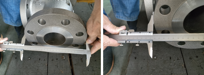
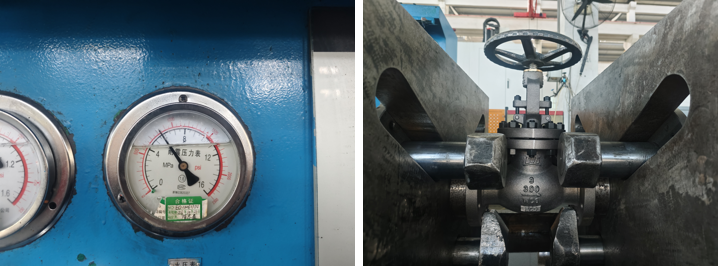
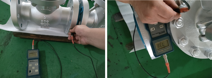
2인치 300LB 글로브 밸브는 BS1873 표준에 따라 제작되었습니다. 밸브 본체는 A494 CU5MCUC 재질로 만들어졌으며, OS&Y 구조, 볼트식 보닛(BB), 플러그형 디스크 등의 구조적 특징을 가지고 있으며, 재질은 NACE MR0175 규격을 준수합니다. 연결 방식은 RF 방식이며, 핸드휠이 장착되어 있습니다. 작동 모드. 제품 매개변수 유형 글로브 밸브 크기 2인치 압력 300파운드 연결 RF 작업 핸드휠 본체 재질 A494 CU5MCUC 디자인 표준 BS1873 대면 ASME B16.10 플랜지 치수 ASME B16.5 시험 및 검사 규정 API 598 온도 -35 ~ 300 °C 적용 가능한 매체 물, 석유 및 가스 특징 1. CU5MCuC 니켈 알루미늄 청동 구조는 부식, 캐비테이션 및 해수 환경에 대한 탁월한 저항성을 제공합니다. 2. RF 플랜지와 핸드휠 작동 방식을 적용한 글로브 밸브 설계는 BS 1873 규격을 준수하여 정확한 유량 조절과 안정적인 차단을 보장합니다. 기술 도면 치수 검사 압력 테스트 스펙트럼