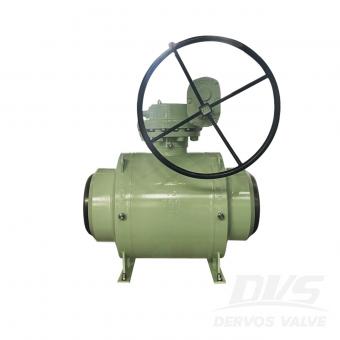
남아프리카공화국의 주요 석유 고객사가 배치한 DVS 슬라이딩 블라인드 밸브 석유 제품, 천연가스 및 화학 용제 간의 빈번한 전환이 필요한 다중 매체 파이프라인 시스템에 적용되었습니다. 설치 이후 시스템은 안정적인 무누출 운전을 달성했습니다. 밸브의 가압 상태 온라인 운전 기능 덕분에 가동 중지 및 감압이 완전히 필요 없어졌으며, 현장 유지보수 안전성이 크게 향상되었습니다. 고객 문제: 잦은 멀티미디어 전환 시 밀봉 불량 및 확실한 절연 부족 고객사는 남아프리카공화국에 위치한 대형 석유 처리 및 저장 회사입니다. 이 회사의 파이프라인 네트워크는 석유 제품, 천연가스, 화학 용제 등 다양한 매체를 빈번하게 전환하며 사용합니다. 매체의 특성이 크게 다르기 때문에, 시스템은 밸브 밀봉 성능, 내식성 및 운영 안전성에 매우 높은 기준을 요구합니다. 기존 방식을 사용하는 동안 게이트 밸브 고객사는 볼 밸브와 관련하여 장기적으로 다음과 같은 중요한 운영 문제에 직면했습니다. 문제 유형 일반 게이트/볼 밸브 성능 실제 운영 영향 밀봉 불량 및 내부 누출 밀봉재는 시간이 지남에 따라 성능이 저하되므로 누출이 전혀 없음을 보장할 수 없습니다. 미디어 유출은 심각한 안전 및 환경 위험을 초래합니다. 정비를 위해서는 가동 중단 및 감압이 필요합니다. 파이프라인은 유지보수 전에 완전히 감압되어야 합니다. 장시간 가동 중단 및 상당한 생산 손실 진정한 양성 격리를 달성할 수 없음 격리는 신뢰성이 제한적인 밀봉 부품에 의존합니다. 매체 전환 중 교차 오염 위험 고객은 다음과 같은 기능을 갖춘 밸브 솔루션을 특별히 요청했습니다. ● 밀봉재에 의존하지 않고 작동 ● 압박 속에서도 운영을 지원합니다 ● 제공 완전한 물리적 고립 DVS 슬라이딩 블라인드 밸브 솔루션: 물리적 격리 + 온라인 작동 + 누출 제로 DVS 슬라이딩 블라인드 밸브는 견고한 블라인드 플레이트를 사용하여 유체의 통로를 물리적으로 차단합니다. 이러한 설계는 기존의 씰 의존형 밸브와 관련된 위험을 근본적으로 제거합니다. 다음 네 가지 기술적 이점은 고객의 운영 문제를 해결하는 데 핵심적인 역할을 했습니다. 누설 없는 완벽한 물리적 격리 견고한 블라인드 플레이트는 유체 흐름을 직접 차단하여 씰 노화 및 씰 파손 문제를 방지합니다. 이를 통해 모든 작동 조건에서 진정한 누출 방지 성능을 보장합니다. 온라인 운영 중단 없이 압박 속에서도 운영 가능 밸브는 시스템의 가압 상태를 유지하면서 열림과 닫힘 위치 사이를 전환할 수 있습니다. 감압이나 �
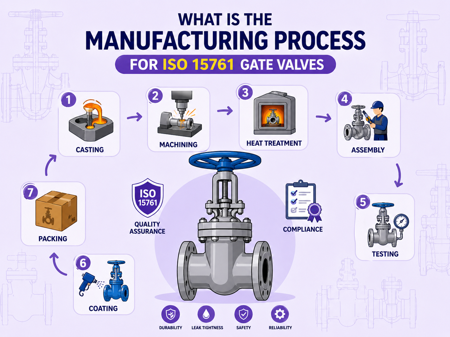
ISO 15761은 석유 및 가스 산업에서 사용되는 소구경 강밸브에 대한 표준으로, DN 15부터 DN 100까지의 크기와 Class 150부터 Class 2500까지의 압력 등급을 포괄합니다. 이 표준은 다음 분야에 적용됩니다. 게이트 밸브 s, 글로브 밸브 및 체크 밸브. 이러한 밸브는 단일 공정으로 생산되는 것이 아니라, 순차적인 제조 공정을 통해 생산됩니다. 각 단계의 품질은 다음 단계에 직접적인 영향을 미칩니다. 이러한 제조 공정을 이해하면 밸브 선정, 규정 준수 검토 및 공급업체 평가 과정에서 중요한 문제점을 보다 효율적으로 파악할 수 있습니다. 전체 제조 공정 1단계: 재료 선택 재질은 적용 가능한 서비스 조건을 결정하며 전체 공정의 출발점입니다. ISO 15761에 따른 일반적인 재료는 다음과 같습니다. ● 석유 및 가스 산업 전반에 사용되는 탄소강 ● 극저온 또는 저온 환경(예: LNG 응용 분야)용 저온 탄소강 ● 부식성 매체용 스테인리스강 서비스에 황화수소(H₂S)가 포함된 경우, 황화물 응력 균열을 방지하기 위해 재료는 NACE MR0175/ISO 15156도 준수해야 합니다. 이 요구사항은 ISO 15761과는 별도로 적용됩니다. 잘못된 재료 선택은 후속 공정 제어로 보완할 수 없습니다. 2단계: 단조 이 단계는 밸브 본체의 내부 품질을 결정합니다. 단조는 가열된 금속을 압력 하에 성형하는 공정으로, 결함 발생 확률이 낮은 조밀한 내부 구조를 만듭니다. 일반적으로 고압 또는 높은 신뢰성이 요구되는 용도에 적합합니다. 800급 이상에서는, 단조체 일반적으로 엔지니어링 실무에서는 내부 결함 위험을 줄이고 구조적 신뢰성을 향상시키기 위해 이러한 방식이 선택되지만, 최종 선택은 프로젝트 사양에 따라 달라집니다. 3단계: 가공 성형 후, 치수 및 밀봉 요구 사항을 충족하기 위해 정밀 가공이 수행됩니다. 밀봉면 가공은 매우 중요한 관리 요소입니다. 시트와 디스크 사이의 접촉면은 지정된 평탄도와 표면 조도를 얻기 위해 여러 번의 가공 및 래핑 공정을 거쳐야 하며, 이는 차단 성능에 직접적인 영향을 미칩니다. 스템 표면 또한 장기간 패킹 밀봉 안정성을 보장하기 위해 낮은 표면 거칠기 요건을 충족해야 합니다. 표면 거칠기가 과도하면 패킹 마모가 가속화되고 작동 중 외부 누출이 발생할 수 있습니다. 4단계: 용접 (밀봉면 경화처리) 이 공정은 밀봉 표면의 성능을 향상시키는 데 사용됩니다. 내마모성 또는 내식성이 요구되는 용도에서는 일반적으로 밀봉 표면에 스텔라이트와 같은 경질 합금을 덧씌워 내성을 향상시킵니다. 용접 과정에서 모재의 과도한 혼합을 방지하고 표면 경도를 낮추기 위해서는 열 입력량과 희석률을 제어해야 합니다. 경화층은 일반적으로 지정된 경도 범위(예: 스텔라이트의 경우 일반적으로 ≥ HRC 35–45)를 충족해야 합니다. 이 공정은 자격을 갖춘 용접공이 용접 절차 사양(WPS), 절차 자격 기록(PQR) 및 추적 가능한 문서를 갖추고 수행해야 합니다. 5단계: 열처리 열처리는 재료의 특성을 향상시키고 잔류 응력을 완화합니다. 이는 필수적인 공정입니다. 단조 후 열처리는 재료가 요구되는 기계적 특성을 충족하고 내부 응력을 제거하는 데 필수적입니다. 이 과정이 없으면 강도와 인성이 불확실해집니다. 용접 후 열처리(PWHT)는 일반적으로 용접 잔류 응력을 제거하기 위해 필요합니다. 황화수소(H₂S)가 함유된 환경에서는 용접 부위의 균열을 방지하기 위해 PWHT가 필수적인 경우가 많습니다. 열처리 기록이나 용광로 추적성을 제공할 수 없는 경우, 재료 성능을 검증할 수 없습니다. 6단계: 표면 처리 이 단계는 보관, 운송 및 사용 중 부식을 방지합니다. ● 탄소강 밸브는 일반적으로 샌드블라스팅 처리 후 부식 방지 페인트로 코팅됩니다. ● 스테인리스강 밸브는 일반적으로 도색하지 않고 산세척 및 부동태화 처리를 거쳐 안정적인 보호층을 형성합니다. 부동태 처리가 되어 있지 않으면 스테인리스강은 염화물 환경에서 공식 부식에 더 취약해집니다. 참고: 저온용 탄소강 밸브는 용융 아연 도금에 적합하지 않습니다. 아연은 저온에서 취성을 유발하여 재료 성능을 저하시킬 수 있습니다. 7단계: 조립 모든 부품은 가공 후 조립됩니다. 조립 품질은 최종 성능에 직접적인 영향을 미칩니다. 주요 통제 지점은 다음과 같습니다. ● 시트 간섭 방지 ● 포장 압축 ● 보닛 볼트 조임 순서 패킹을 과도하게 압축하면 작동 토크가 증가하여 고착될 수 있습니다. 압축이 부족하면 출하 전에도 누출이 발생할 수 있습니다. 볼트를 잘못 조이면(예: 대각선 순서를 따르지 않으면) 플랜지 응력이 불균형해지고 밀봉 성능이 저하될 수 있습니다. 이러한 문제는 육안으로 확인할 수 없으므로 조립 기록 및 테스트 데이터를 통해 검증해야 합니다. 8단계: 압력 테스트 이는 배송 전 최종 필수 확인 절차입니다. 시험은 일반적으로 ISO 5208에 따라 수행됩니다. API 598 , 포함: ● 쉘 테스트: 가압 상태에서 누출이 없는지 확인합니다. ● 밀폐 테스트: 닫힌 위치에서의 밀폐 성능을 확인합니다. ● 뒷좌석 테스트: 상단 스템 밀봉 상태 확인 ISO 5208에 따라 누출률은 A등급부터 D등급까지 분류됩니다. 구매 문서에 명시되지 않은 경우, 제조업체는 표준을 준수하지만 실제 사용 요구 사항을 충족하지 못할 수 있는 더 높은 허용 누출 등급을 적용할 수 있습니다. 결론 ISO 15761 밸브의 제조 품질은 최종 압력 테스트만으로 결정되는 것이 아니라 전체 공정에 의해 결정됩니다. 재료 적합성, 블랭크의 내부 무결성, 밀봉면 가공 품질 및 열처리 완료 여부는 육안 검사로는 확인할 수 없습니다. 이러한 사항들은 추적 가능한 공정 문서에 의존합니다. 공급업체 평가에서 단일 시험 보고서보다는 전체 공정 기록이 일반적으로 더 가치가 있습니다. 자주 묻는 질문 Q1: 구매 시 단조 밸브 본체와 주조 밸브 본체를 어떻게 구분할 수 있습니까? 자재 인증서 외에도 공급업체는 다음 사항을 제공해야 합니다. ● 단조품: 단조 기록 및 열처리 보고서 ● 캐스팅: RT 또는 UT 보고서 인증서만으로는 실제 제조 공정을 확인하기에 충분하지 ...
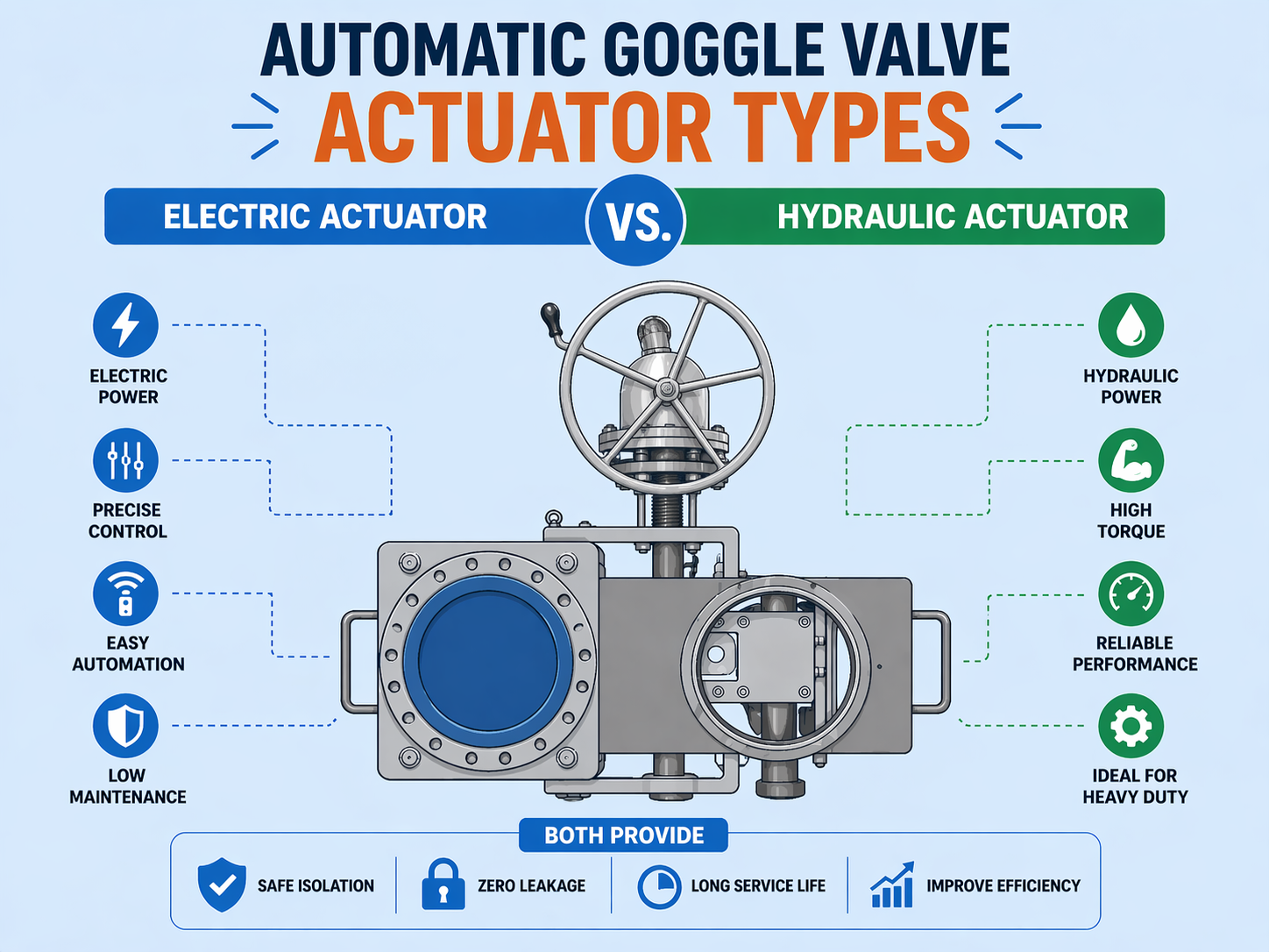
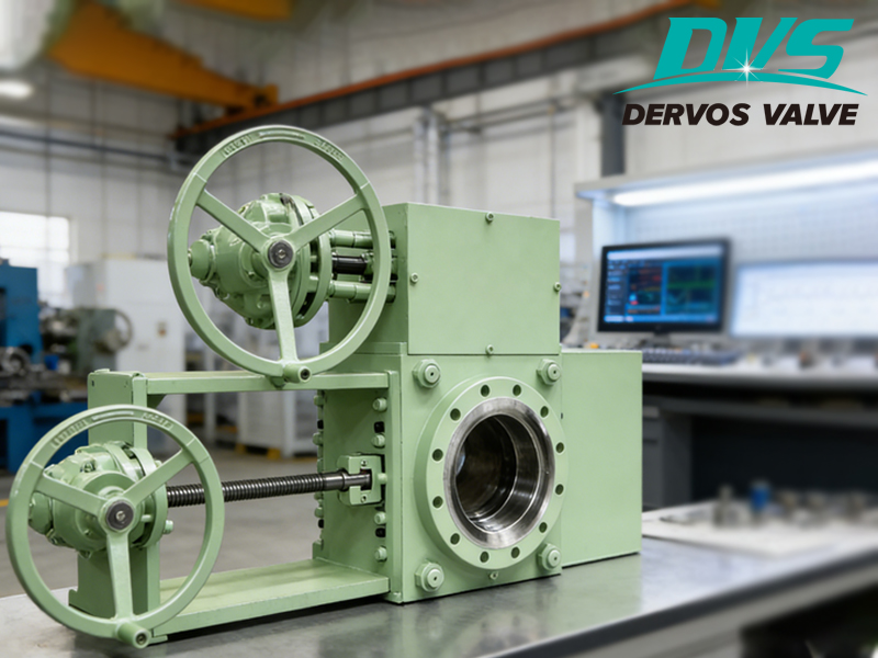
원격 작동이나 빈번한 전환이 필요한 애플리케이션에서는 자동 기능이 사용됩니다. 라인 블라인드 밸브 일반적으로 전기식 또는 유압식 작동 장치를 갖추고 있습니다. 두 시스템의 근본적인 차이점은 사용 가능 여부에 있는 것이 아니라, 부하 용량, 반응 특성, 환경 적응성 및 시스템 복잡성에 있습니다. 1. 전기 작동식 (전기 작동식 라인 블라인드 밸브) 전기 구동 방식은 모터와 감속 기어박스를 결합하여 토크를 발생시키고, 이 토크로 블라인드 플레이트를 구동하여 스위칭 작동을 완료합니다. 선택 논리: ● 현장의 전력 공급이 안정적이라면 → 전기 구동 방식을 우선적으로 고려해야 합니다. ● 원격 제어 또는 자동화 통합(DCS/PLC)이 필요한 경우 → 전기 구동 방식이 더 간단합니다 ● 스위칭 주파수가 비교적 높을 경우 → 전기 구동 방식은 작동 속도를 더 효과적으로 제어할 수 있습니다. 주요 특징: ● 간편한 제어: 제어 시스템에 직접 통합하여 원격 작동 및 위치 피드백이 가능합니다. ● 컴팩트한 구조: 추가 유압 동력 장치가 필요하지 않습니다. ● 유지보수 요구사항 감소: 정기 점검은 주로 모터와 기어박스에 집중됩니다. 제한 사항: ● 밸브 크기가 크거나 높은 추력이 필요한 경우 → 전기 구동 장치의 토크가 부족할 수 있습니다. ● 환경이 고온, 위험(폭발성) 또는 분진이 많은 경우 → 더 높은 전기 보호 기준(예: ATEX)이 필요합니다. ● 전원 공급이 불안정하거나 자주 중단될 경우 → 신뢰성이 저하될 수 있습니다. 결론: 표준 자동화 요구 사항과 적당한 부하 조건이 필요한 애플리케이션의 경우, 일반적으로 전기 구동 방식이 선호되는 솔루션입니다. 2. 유압 작동 (유압식 작동) 라인 블라인드 밸브 ) 유압 구동 방식은 유압 유체 압력을 통해 추력을 발생시키므로 고하중 적용 분야에 적합합니다. 선택 논리: ● 밸브 크기가 큰 경우(예: DN300 이상) → 유압 작동 방식을 우선적으로 고려해야 합니다. ● 높은 추력이 필요하거나 저항/걸림 현상을 극복해야 하는 경우 → 유압식 작동이 더 안정적입니다. ● 현장에 이미 유압 시스템이 설치되어 있는 경우 → 통합 비용이 절감됩니다 주요 특징: ● 높은 추력 출력: 고하중 막힘판 또는 고압 파이프라인에 적합합니다. ● 안정적인 작동: 충격 부하에 대한 강력한 저항력을 바탕으로 지속적인 출력을 제공합니다. ● 우수한 제어성: 압력 조절을 통해 정밀한 제어가 가능합니다. 제한 사항: ● 현장에 유압 동력 장치가 없는 경우 → 시스템 복잡성이 증가합니다. ● 주변 온도 변화가 클 경우 → 유압유 성능이 변동될 수 있습니다. ● 유지보수가 불충분할 경우 → 누수 문제가 발생할 가능성이 높아집니다 결론: 높은 부하와 높은 신뢰성이 요구되는 애플리케이션의 경우 유압 구동 방식이 더 적합한 선택입니다. 3. 전기식 vs. 유압식: 주요 선택 기준 일반적인 비교보다는, 다음은 엔지니어링 기반의 직접적인 선택 논리를 제시합니다. ● 높은 추력이 필요한 경우 → 유압식 작동 방식을 선택하십시오 ● 시스템 단순성이 최우선이라면 → 전기 구동 방식을 선택하세요 ● 원격 자동화 및 제어가 필요한 경우 → 전기 구동 방식이 선호됩니다 ● 작동 조건이 가혹한 경우(고온/과부하/고착 위험) → 유압 작동 방식이 더 안정적입니다. 4. 일반적인 적용 시나리오 ● 증기 또는 고온 파이프라인용 (예: 600등급/F22 재질) → 열 변형이나 고착 위험이 있는 경우 유압 작동 방식을 우선적으로 고려해야 합니다. ● 석유화학 설비의 유지 보수 격리(중간 정도의 스위칭 빈도): → 제어 시스템과의 통합이 필요한 경우, 전기 구동 방식이 더 적합합니다. ● 대구경 배관(DN400 이상 슬라이딩 라인 블라인드 밸브)의 경우: → 수동 조작이 어려운 경우 일반적으로 유압 작동 방식이 채택됩니다. ● 공간이 제한적이거나 기존 건물을 개조하는 프로젝트의 경우: → 유압 시스템 설치가 현실적으로 불가능하다면 전기 구동 방식을 우선적으로 고려해야 합니다. 5. 흔히 저지르는 선택 실수 실수 1: 추진력 요구 사항을 무시하고 자동화에만 집중하는 것 원격 제어만 고려하고 추력 요구 사항을 간과할 경우, 전기 액추에이터의 크기가 부족하여 작동 불량이 발생할 수 있습니다. 두 번째 실수: 환경적 요인을 무시하는 것 고온 환경이나 옥외 환경에서 적절한 보호 등급 없이 전기 구동 장치를 사용할 경우 고장률이 증가합니다. 세 번째 실수: 유압 시스템의 부적절한 유지 관리 유압 시스템이 제대로 유지 관리되지 않으면 누출이나 압력 변동이 밸브 작동에 직접적인 영향을 미칩니다. 6. 공학적 결론 ● 부하가 높고 신뢰성이 최우선인 경우 → 유압 구동 방식을 선택하십시오 ● 시스템의 단순성과 자동화가 우선이라면 → 전기 구동 방식을 선택하십시오. ● 불확실한 경우 → 먼저 필요한 추력을 계산한 다음 적절한 작동 방식을 결정하십시오. 질문과 답변 Q1: 자동 라인 블라인드 밸브에는 항상 유압 작동이 필요한가요? 반드시 그런 것은 아닙니다. 밸브 크기가 비교적 작고 추력 요구량이 적당하다면 전기 구동 방식으로도 충분히 요구 사항을 충족할 수 있습니다. Q2: 전기 구동 방식이 유압 구동 방식을 대체할 수 있습니까? 필요한 부하가 모터의 처리 능력 범위 내에 있으면 모터를 대체품으로 사용할 수 있습니다. 하지만 필요한 토크가 액추에이터의 용량을 초과하면 사용할 수 없습니다. 질문 3: 유압식 작동 방식이 더 신뢰할 수 있습니까? 고부하 또는 극한 작동 조건에서는 유압 구동 방식이 일반적으로 더 안정적입니다. 표준 조건에서는 두 방식 간의 신뢰성 차이가 미미합니다. 질문 4: 작동 방식을 빠르게 확인하는 방법은 무엇입니까? 주요 위험 요소가 구동력 부족인 경우 → 유압식 작동 방식을 선택하십시오. 제어 및 시스템 통합이 주요 요구 사항이라면 → 전기 구동 방식을 선택하십시오. Q5: 하나의 자동 라인 블라인드 밸브에 두 가지 작동 방식을 모두 구성할 수 있습니까? 예. 예를 들어, 전기식 + 수동식 또는 유압식 + 수동식 구성을 백업으로 사용할 수 있습니다. 하지만 전기식과 유압식 구동 방식을 모두 주 구동 ...
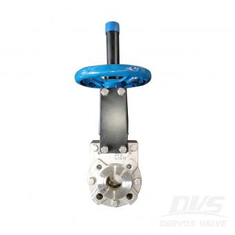

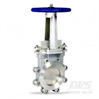
2" 150LB 나이프 게이트 밸브는 MFS 표준에 따라 제작되었습니다. 밸브 본체는 ASTM A351 CF8로 제작되었습니다. 양측 밀봉 및 흐름 편향 장치의 구조적 특성을 가지고 있습니다. 연결 모드는 러그입니다. 그리고 핸드 휠 작동 모드가 있습니다.
지불:
30% when order confirmed, 70% before shipment제품 원산지:
China색:
Customization배송 포트:
Shanghai, China리드 타임:
30~60 days Ex Works after order confirmationMaterial:
ASTM A351 CF8Method of Operation:
Hand Wheel제품 설명
|
유형 |
나이프 게이트 밸브 |
|
크기 |
2" |
|
압력 |
150LB |
|
연결 |
돌기 |
|
작업 |
핸드휠 |
|
본체 재질 |
ASTM A351 CF8 |
|
디자인 기준 |
MFS |
|
플랜지 연결 |
AS2129 표 E |
|
면 대면 |
EN558 |
|
테스트 및 검사 코드 |
MSS SP-81 |
|
적용 가능한 매체 |
물, 석유 및 가스 |
특징
1. 간단한 구조, 제조 및 유지 관리가 용이합니다.
2. 간단한 구조, 낮은 유체 저항, 우수한 밀봉 성능 및 빠른 개폐.
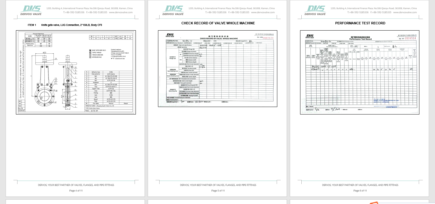
기술 도면

치수 확인

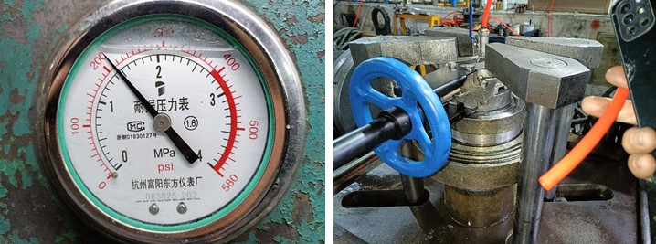
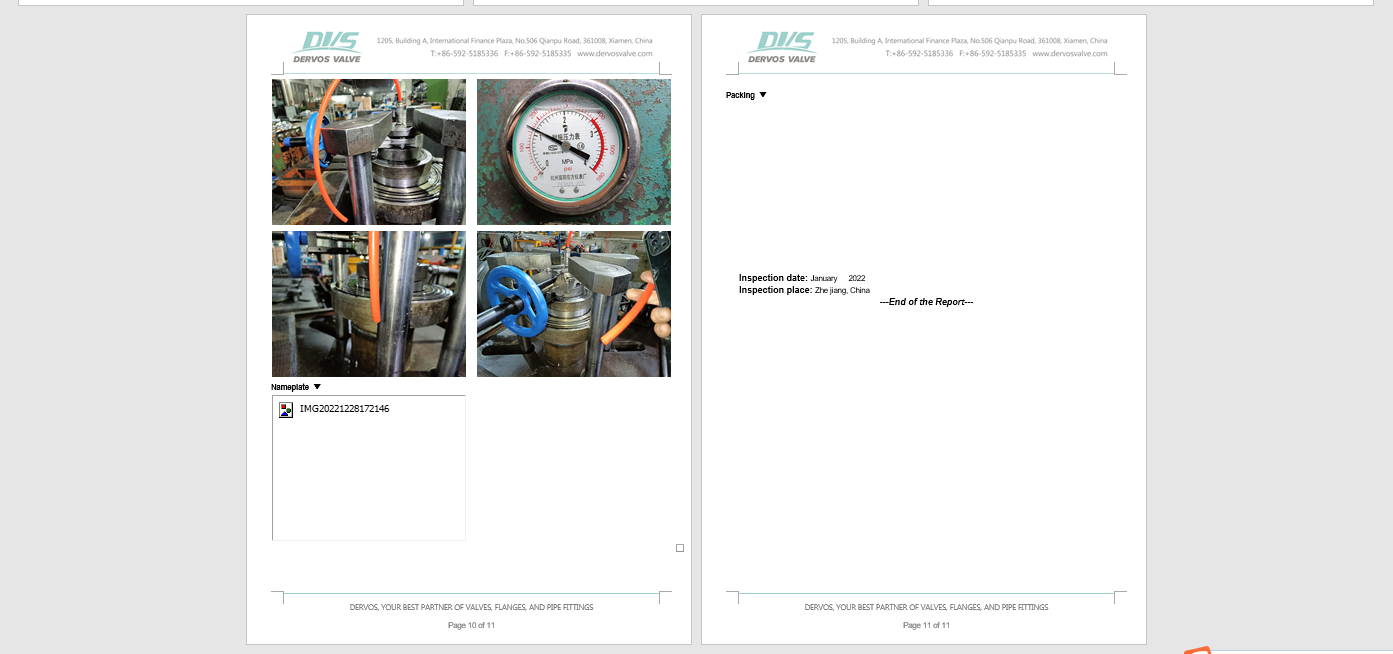
압력 테스트
명판 및 포장

검사 보고서


에 관심이 있다면 우리의 제품과한 자세한 내용을 알고 싶다면,메시지를 남겨주십시오 여기,우리가 응답할 것입니다 당신은 빨리 우리가 할 수 있습니다.
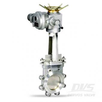
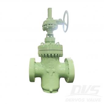
mss-sp-81에 따라 설계된 6 인치 스텐레스 강 게이트 밸브는 클래스 150 및 전기 액츄에이터에 러그 유형 연결을 갖추고 있습니다. 빠른 세부 사항 유형 칼 게이트 밸브 크기 6 인치 설계 압력 아니 150 구성 칼 게이트 밸브 연결 타입 돌기 유형 작업 유형 전기 같은 액추에이터 바디 재료 ASTM a351 cf8 트림 재료 ss304 디자인 코드 mss sp81 매질 물, 석유와 가스 유래 중국 관련 지식나이프 게이트 밸브는 무엇에 사용됩니까? 나이프 게이트 밸브는 원래 제지 산업을 위해 설계되었습니다. 나이프 게이트 밸브는 슬러리 액체와 같이 가장 부식성, 침식성 및 연마 성이 우수한 고체 미립자가있는 중질 액체에 특히 적용 할 수 있습니다. 쐐기 게이트 밸브에 비해 나이프 게이트 밸브는 엔드-투-엔드 치수가 짧고 무게가 가볍습니다. 또한 나이프 밸브에는 슬러리와 점성 매체를 절단하기 위해 디스크가 더 날카 로워졌습니다. 웨지 게이트 밸브와 나이프 게이트 밸브는 유량을 조절하지 않는 온-오프 기능에만 사용할 수 있습니다. dervos 고객 서비스dervos 고객 서비스를 통해 밸브를 구매하기 전, 도중 및 후에 걱정할 필요가 없습니다. 사전 판매우리는 제 시간에 응답하고 귀하의 요청에 따라 기술 지원을 제공합니다. 주문우리는 공장 및 고객과 생산 세부 사항을 확인합니다. 판매 확인서도 발송됩니다. 생산하는 동안 주문 상태를 알려주는 주간 보고서를 보내드립니다. 선적하기 전에 상황을 알려주기 위해 납품서가 발송됩니다. 18 개월 보증 dervos는 항상 제품에 대한 책임이 있습니다. 우리는 고객에게 걱정없이 18 개월 보증을 제공 할 것입니다.
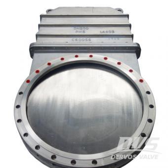
스테인레스 스틸 나이프 게이트 밸브는 dn800 pn6 플랜지 엔드 및 기어 박스 작동으로 설계되었습니다. 연성 시트 나이프 게이트 밸브에는 단방향 밀봉이 있습니다. 빠른 세부 사항 유형 문 판막 크기 dn800 설계 압력 pn6 구성 단방향, 부드러운 자리 연결 타입 플랜지 종료 작업 유형 변속 장치 움직이는 바디 재료 cf8m 디스크 재료 ss316l 줄기 재료 ss316 시트 재료 ptfe 디자인 코드 mss sp81 매질 물, 석유와 가스 유래 중국 치수 확인 압력 테스트
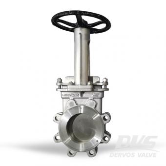
The 나이프 게이트는 양방향 MSS-SP-81 에 따라 설계된 러그 형 밸브 및 산업 서비스 애플리케이션. The 차체와 시트의 디자인은 막힘 방지 산업에서 부유 물질을 차단하십시오.
DN150 PN10 단방향 나이프 게이트 밸브 단일 피스의 스테인리스 스틸 본체 디자인이 특징이며 범용에서 가혹한 매체에 이르는 응용 분야에서 테스트된 성능을 제공합니다.
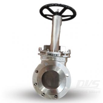
러그 유형 나이프 게이트 밸브는 스테인리스 스틸 CF8,로 만든 mss-sp-81.에 따라 설계되었습니다. 4인치 게이트 밸브에는 150LB 플랜지 연결 및 핸드휠 작동이 있습니다.