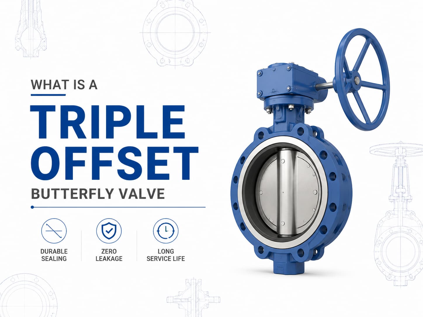
A 트리플 오프셋 버터플라이 밸브은 기존의 탄성 시트형 또는 더블 오프셋 버터플라이 밸브가 압력, 온도 또는 누설 요구사항을 충족하지 못하는 응용 분야를 위해 설계된 고성능 차단 밸브입니다. 3중 오프셋 밀봉 설계를 사용하여 작동 중 디스크와 시트 사이의 마찰을 줄인 금속 대 금속 밀봉 메커니즘을 구현하므로 오일 및 가스, 석유화학, 발전, LNG, 증기 및 산업 공정 시스템과 같은 까다로운 서비스에 적합합니다. 트리플 오프셋 버터플라이 밸브 설계 및 작동 원리 디스크와 시트의 중심선에 샤프트가 위치하는 동심형 버터플라이 밸브와 달리, 트리플 오프셋 버터플라이 밸브은 세 가지 독립적인 기하학적 오프셋을 적용합니다. 첫 번째 오프셋은 샤프트를 밸브 본체의 중심선에서 이동시키고, 두 번째 오프셋은 샤프트를 배관 중심선에서 이동시키며, 세 번째 오프셋은 원형 밀봉 형상 대신 원뿔형 밀봉 표면을 적용합니다. 이 형상은 회전이 시작된 직후 디스크가 시트에서 떨어져 이동하도록 하여 밀봉 표면 사이의 마찰을 제거합니다. 이 설계의 주요 장점은 밀봉력이 연질 재료의 지속적인 압축이 아니라 토크에 의해 생성된다는 점입니다. 고온 서비스가 필요한 경우, 엘라스토머 시트는 높은 온도에서 열화될 수 있으므로 금속 시트형 트리플 오프셋 버터플라이 밸브이 자주 선호됩니다. 매체에 마모성 입자 또는 부식성 화학물질이 포함된 경우, 장기간 작동 중 침식, 부식 및 누설을 방지하기 위해 디스크, 시트 및 본체의 재질 선택이 매우 중요합니다. 트리플 오프셋 버터플라이 밸브 표준 및 재질 트리플 오프셋 버터플라이 밸브는 일반적으로 API 609, EN 593 및 ISO 5752와 같은 표준에 따라 제조되며, 설계 요구사항에 따라 압력 등급은 Class 150부터 Class 600 이상까지 다양합니다. 일반적인 재질에는 탄소강, 스테인리스강, 듀플렉스 스테인리스강, 알루미늄 청동 및 니켈 기반 합금이 포함됩니다. 부식성 해수 응용 분야에서는 C95500 또는 C95800과 같은 알루미늄 청동 합금이 선택될 수 있으며, 사워 서비스 응용 분야에서는 NACE MR0175/ISO 15156 요구사항을 준수하는 재질이 필요할 수 있습니다. 트리플 오프셋 버터플라이 밸브 밀봉 성능 및 누설 제어 트리플 오프셋 버터플라이 밸브의 밀봉 성능은 밀봉 링, 시트 표면 마감, 작동 토크 및 재질 호환성 간의 상호작용에 따라 결정됩니다. 밀봉 표면은 최종 폐쇄 위치에서만 접촉하므로 기존 버터플라이 밸브 설계와 비교하여 기계적 마모가 크게 감소합니다. 중요한 차단 작업에서 제로 누설이
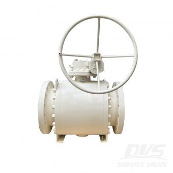
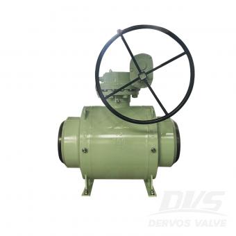
볼 밸브와 플러그 밸브는 모두 산업용 배관 시스템에서 개폐 제어 및 차단에 사용되는 90도 회전식 밸브입니다. 두 밸브는 유사한 작동 원리를 공유하지만, 내부 설계 차이로 인해 특히 밀봉 성능, 압력 허용 능력, 작동 토크, 유지보수 요구 사항 및 다양한 유체에 대한 적합성 측면에서 서로 다른 성능 특성을 보입니다. 볼 밸브와 플러그 밸브 중 선택은 밸브 유형에 대한 선호보다 실제 운전 조건을 기준으로 해야 합니다. 적용 분야에서 긴밀한 차단, 빈번한 작동, 낮은 작동 토크가 필요하다면 볼 밸브가 흔히 선호됩니다. 시스템에 오염된 유체, 마모성 입자 또는 큰 유로가 포함되는 경우 플러그 밸브가 더 높은 신뢰성을 제공할 수 있습니다. 설계 차이와 밀봉 성능 은볼 밸브는 관통 구멍이 뚫린 구형 차단 요소를 사용합니다. 밸브가 열리면 관통 구멍이 배관과 정렬되어 거의 제한 없는 유로를 제공합니다. 90도 회전하면 볼의 막힌 부분이 통로를 차단하여 차단 기능을 수행합니다. 플러그 밸브는 중앙을 관통하는 유로가 있는 원통형 또는 원추형 플러그를 사용합니다. 플러그는 본체 내부에서 회전하여 유량을 제어합니다. 설계에 따라 플러그 밸브는 윤활식, 슬리브식 또는 비윤활식으로 제작될 수 있으며, 각 구조는 서로 다른 밀봉 특성을 제공합니다. 밀봉 메커니즘은 두 밸브의 주요 차이점 중 하나입니다. 볼 밸브는 일반적으로 소프트 시트, 금속 시트 또는 두 가지를 조합한 방식을 사용하여 신뢰성 있는 차단을 달성합니다. 시스템에서 특히 가스 서비스나 중요 공정 적용 분야와 같이 기포 누설 없는 차단이 필요한 경우, 적절히 선정된 볼 밸브는 우수한 밀봉 성능을 제공할 수 있습니다. 플러그 밸브는 플러그와 밸브 본체 또는 슬리브 사이의 접촉에 의존합니다. 윤활식 플러그 밸브는 플러그와 본체 사이에 주입된 실란트를 사용하여 마찰을 줄이고 밀봉 성능을 향상시킵니다. 이 설계는 실란트가 밀봉 표면을 보호하는 데 도움을 주기 때문에 유체에 오염물이 포함된 적용 분야에서 우수한 성능을 발휘할 수 있습니다. 적용 시 고려 사항 운전 조건은 볼 밸브 또는플러그 밸브중 어느 것이 더 적합한지를 결정합니다. 볼 밸브는 신뢰성 있는 차단이 필요한 석유 및 가스, 석유화학, LNG, 화학 처리 및 발전 산업에서 널리 사용됩니다. 플로팅 볼 밸브는 일반적으로 낮은 압력 시스템에 적용되며, 트러니언 장착 볼 밸브는 트러니언 지지가 작동 토크를 줄여주기 때문에 대구경 및 높은 압력 등급에서 선호됩니다. 밸브가 빈�
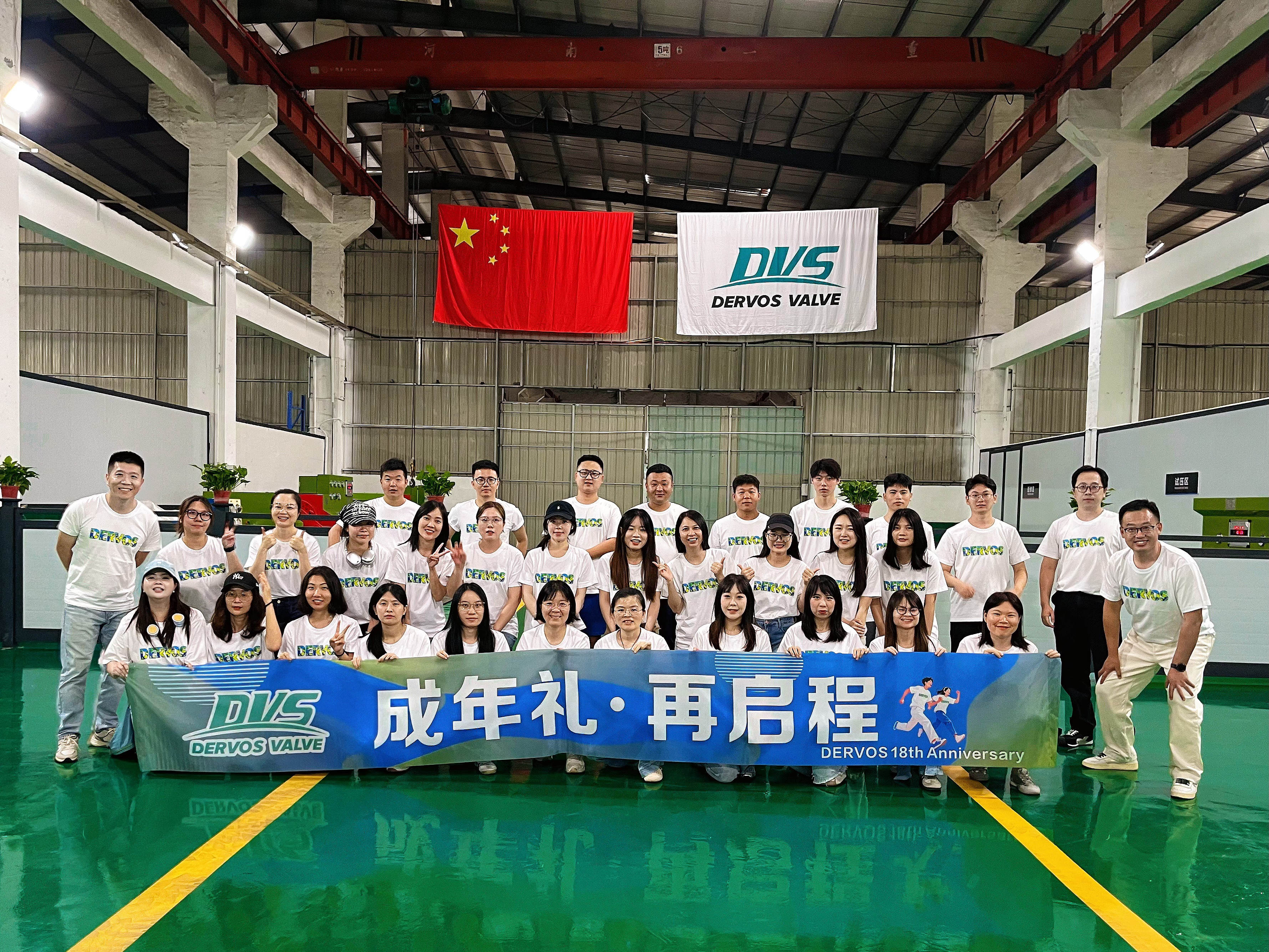
2026년, DERVOS VALVE는 자랑스럽게 창립 18주년을 기념하며 회사의 여정에서 중요한 이정표를 맞이합니다. 이 특별한 행사를 기념하기 위해 DERVOS VALVE는 3일간의 기념 축하 행사를 개최하여 전 직원이 함께 모여 지난 18년간 회사의 성과를 되돌아보고, 미래 발전을 전망하며, 의미 있는 활동과 공유 경험을 통해 팀 결속력을 더욱 강화했습니다. 18년의 성장 되돌아보기 원자재 관리와 정밀 가공에서부터 조립 및 제품 시험에 이르기까지, 모든 생산 단계는 DERVOS VALVE의 변함없는 품질에 대한 헌신을 보여줍니다. 지난 18년 동안 DERVOS VALVE는 제품 품질과 고객 서비스 역량을 향상시키는 동시에 제조 시스템을 지속적으로 개선해 왔습니다. 오늘날 우리의 산업용 밸브는 석유 및 가스, 화학, 발전, 수처리, LNG, 및 기타 산업 분야 전반에서 널리 사용되고 있으며 전 세계 고객에게 신뢰할 수 있는 밸브 솔루션을 제공하고 있습니다. 미래 발전을 위한 공감대 형성 기념 행사 기간 동안 DERVOS VALVE는 또한 상반기 소통 회의를 개최했습니다. 회의에서는 올해 상반기 회사의 실적을 검토하고 향후 발전을 위한 주요 목표를 제시했습니다. 각 부서를 대표하는 인사들이 생산 관리, 품질 개선 및 부서 간 협업, 실무 경험 공유, 성과 검토 및 향후 목표를 함께 논의하는 내용. 이번 회의는 부서 간 소통을 더욱 강화하고 팀의 정렬을 공고히 했으며, 회사의 장기적인 발전에 새로운 동력을 불어넣었다. 자연을 함께 품다 회사 창립 기념 활동 외에도 DERVOS VALVE는 자연의 아름다움을 체험하는 단체 여행을 조직했다. 아름다운 풍경에 둘러싸여 직원들은 경치 좋은 환경을 즐기고 편안하고 즐거운 분위기 속에서 지역 문화를 탐방했다. 이번 여행은 긴장을 풀 수 있는 기회를 제공하는 동시에 동료들 간의 관계를 더욱 돈독하게 했다. 이 뜻깊은 경험은 창립 기념 행사를 더욱 풍성하게 했으며, 팀 정신을 강화하고 앞으로의 업무를 위한 새로운 에너지로 모두에게 영감을 주었다. 18년의 헌신, 미래를 향하여 18년은 성장과 성취를 의미할 뿐만 아니라 새로운 장의 시작이기도 하다. 창립 이래 DERVOS VALVE는 산업용 밸브의 설계, 제조 및 글로벌 공급에 전념해 왔다. 통해 제품 개발, 제조 역량 및 품질 관리의 지속적인 개선을 통해 회사는 전 세계 다양한 산업 분야의 고객들에게 신뢰할 수 있는 밸브 제품과 기술 지원을 제공해 왔다. 앞으로 DERVOS VALVE는 제품 혁신, 제조 우수성 및 장기적인 파트너십에 계속 집중하여 전 세계 고객에게 신뢰할 수 있는
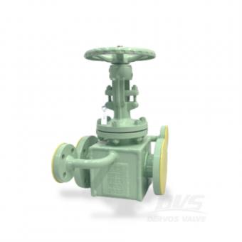

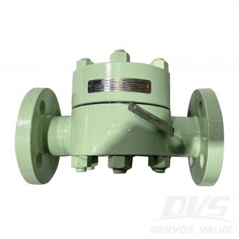
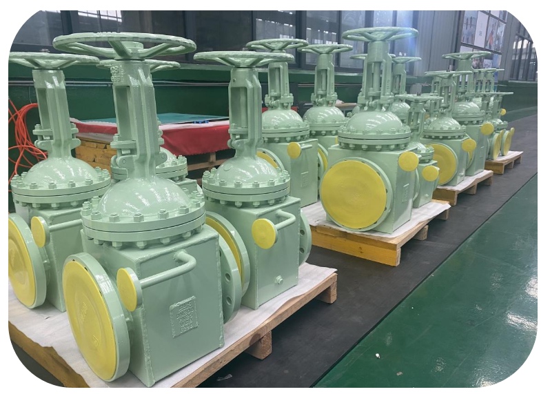
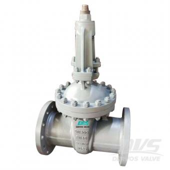
이 DN50 게이트 밸브는 우리의 새로운 이중 가열 재킷 게이트 밸브의 최근 배치 중 하나입니다.직경 범위 from DN50 DN250. 이중 재킷은 밸브 본체를 방지합니다. 부식 중 단열재로 매체.
지불:
30% when order confirmed, 70% before shipment제품 원산지:
China색:
Customization배송 포트:
Shanghai, China리드 타임:
30~60 days Ex Works after order confirmationMaterial:
WCBMethod of Operation:
HD-OP빠른 세부 사항
유형 | 게이트 밸브 |
공칭 직경 | DN50 |
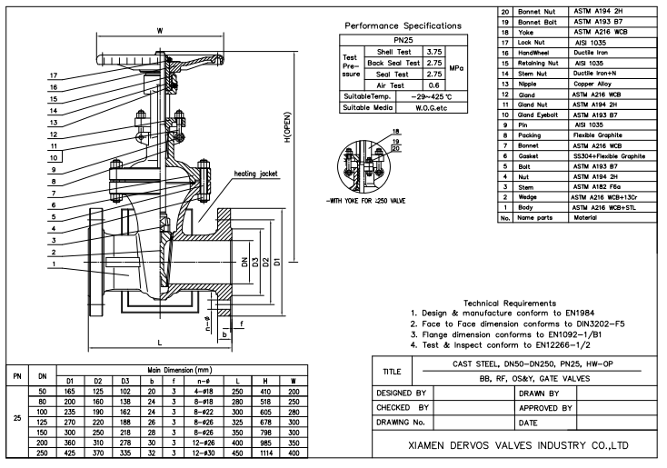
공칭 압력 | PN25 |
구성 | 이중 재킷 유형, OS & Y, 볼트 보닛 |
연결 | rf |
디자인 & 제조 | EN1984 |
f toF 치수 | DIN3202 |
테스트 & 검사 | EN12266-1 / 2 |
바디 재질 | WCB |
쐐기 재료 | WCB + 13Cr |
시트 재료 | STL |
기온 범위 | -29 ~ 425 ℃ |
미디어 | W.O.G.etc |
풍모
더블 재킷 - 밸브 몸체가 부터 부식 중 단열재로 매체.
기술 도면
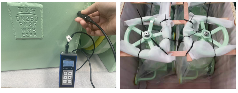
증인 테스트
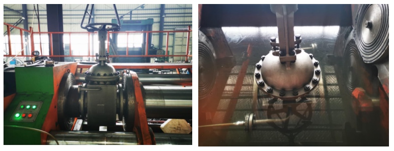
코트 두께 체크 & 포장
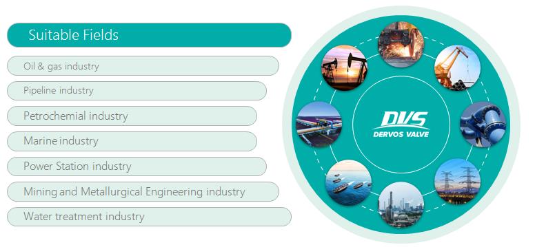
제품 응용
Dervos 밸브는 석유 화학, 파이프 라인, 석유와 같은 다양한 산업에서 널리 사용될 수 있습니다. & 가스, 해양, 수처리, 발전소 산업 등
에 관심이 있다면 우리의 제품과한 자세한 내용을 알고 싶다면,메시지를 남겨주십시오 여기,우리가 응답할 것입니다 당신은 빨리 우리가 할 수 있습니다.

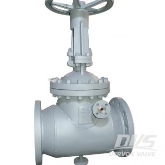
기어 박스 및 600엘b rf 플랜지가있는 16 인치 캐스트 스틸 게이트 밸브는 API 600에 따라 설계되었습니다. 볼트 형 보닛 게이트 밸브는 상승 스템, 탄성 웨지 및 금속 시트에 특징이 있습니다. 빠른 세부 사항 유형 문 판막 크기 16 " 압력 class600 구성 볼트 보닛, 상승 스템, OS 및 플렉시블 웨지, 금속 시트 연결 rf 플랜지 조작 변속 장치 디자인 코드 API 600 면 대면 asme b16.10 플랜지 끝 asme b16.5 압력 및 온도 asme b16.34 테스트 & amp; 검사 API 598 바디 재료 a216 wcb 트림 재료 트림 5 온도 범위 -29 ℃ ~ + 425 ℃ 매질 물, 기름 및 가스 유래 중국 치수 & amp; 재료 클래스 600 nps 에 2 2 1/2 삼 4 6 8 10 12 14 16 18 20 24 dn mm 50 65 80 100 150 200 250 300 350 400 450 500 600 l-l1(rf-bw) 에 11.5 13 14 17 22 26 31 33 35 39 43 47 55 mm 292 330 356 432 559 660 787 838 889 991 1092 1194 1397 l2(rtj) 에 11.625 13.125 14.125 17.125 22.125 26.125 31.125 33.125 35.125 39.125 43.125 47.25 55.375 mm 295 333 359 435 562 664 791 841 892 994 1095 1200 1407 h(열다) 에 18.625 21.75 23.375 28 1/16 38 3/16 44 3/16 52.375 59 13/16 68.125 72.25 90.125 98 13/16 119 mm 474 553 593 713 970 1122 1330 1519 1730 1835 2290 2510 3022 승 에 9.875 9.875 11 13/16 13.75 19 11/16 22 1/16 28.375 24 24 24 24 30 30 mm 250 250 300 350 500 560 720 610 * 610 * 610 * 610 * 760 * 760 * wt(킬로그램) rf 41 58 88 131 253 413 623 784 1288 1820 2150 2540 4080 bw 35 50 68 104 208 328 496 637 1120 1448 1828 2201 3360 * 수동 기어 오퍼레이터 권장 아니 부품 이름 탄소 강철에서 ASTM으로 합금 강철에서 ASTM으로 스테인리스 강철에서 ASTM으로 wcb lcb 화장실 화장실 c5 cf8 cf8m cf3 cf3m 1 신체 a216 화장실 a350 lcb a217 화장실 a217 화장실 a217 c5 a351 cf8 a351 cf8m a351 cf3 a351 cf3m 2 좌석 링 a105 a350 lf2 a182 f11 a182 f22 a182 f5 a182 f304 a182 f316 a182 f304l a182 f316l 삼 쐐기 a216 화장실 a350 lcb a217 화장실 a217 화장실 a217 c5 a351 cf8 a351 cf8m a351 cf3 a351 cf3m 4 줄기 a182 f6 a182 f6 a182 f304 a182 f304 a182 f316 a182 f304l a182 f316l 5 보닛 너트 a194 2 시간 a194 4 a194 7 a194 8 6 보닛 볼트 a193 b7 a320 l7 a193 b16 a193 b8 7 틈 메우는 물건 ss 나선형 상처 흑연 또는 ss 나선형 상처 ptfe 8 보닛 a216 화장실 a352 lcb a217 화장실 a217 화장실 a217 c5 a351 cf8 a351 cf8m a351 cf3 a351 cf3m 9 뒷좌석 부싱 a182 f6 a182 f6 a182 f304 a182 f304 a182 f316 a182 f304l a182 f316l 10 줄기 포장 흑연 또는 PTFE 11 칸델라 a182 f6 a182 f6 a182 f304 a182 f304 a182 f304 a182 f304 a182 f316 a182 f304l a182 f316l 12 글 랜드 너트 a194 2 시간 a194 8 13 글 랜드 아이 볼트 a193 b7 a193 b8 14 핀 탄소강 또는 스테인리스 강철 15 선 a182 f6 a182 f304 a182 f316 a182 f304l a182 f316l 16 글 랜드 플랜지 a216 화장실 a351 cf8 17 줄기 너트 a439 d2 또는 b148-952a 18 젖꼭지 탄소강 또는 스테인리스 강철 19 유지 너트 탄소강 20 핸드 휠 연성 철 또는 탄소 강철 21 명판 스테인레스 스틸 또는 알루미늄 22 잠금 너트 카본 스티l
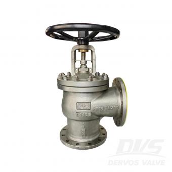
볼트 보닛 게이트 밸브는 en1984 설계 표준, 돌출면 플랜지 연결, 외부 스크류 및 요크, 핸드 휠 작동, gp240gp 바디 / 보닛 / 웨지 재료, f6a 스템, 금속 씰 / 시트를 따릅니다. 빠른 세부 사항 유형 게이트 밸브 크기 dn200 설계 압력 pn40 구성 볼트 보닛 게이트 밸브 연결 타입 돌출면 플랜지 연결 조작 핸드 휠 디자인 코드 1984 년 면 대면 식사 3202 연결 종료 ko 1092-1 테스트 & amp; 검사 ko 12266-1 바디 재료 gp240gh 온도 범위 -29 ~ 425 ℃ 신청 울다
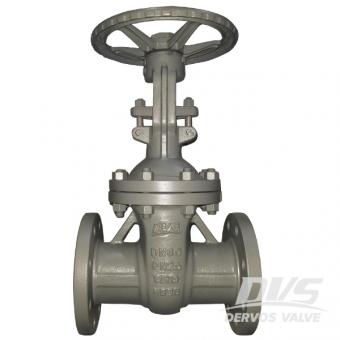
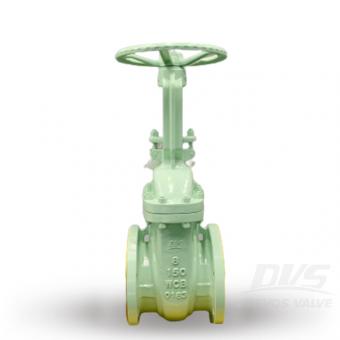
dn80 pn25 게이트 밸브는 1984 년에 따라 설계되었습니다. 볼트 형 보닛, 외부 요크 및 핸드 휠과 같은 밸브의 공통 부품으로 본체는 1.0619와 13cr로 구성됩니다. 신체, 보닛, 시트 및 기타 부품을 포함한 기타 부품은 추적 가능하도록 약속됩니다. 빠른 세부 사항 유형 게이트 밸브 공칭 직경 dn80 공칭 압력 pn25 구성 b.b; OS & Y; 연결 rf 조작 핸드 휠 디자인 및 제조 1984 년 끝으로 종료 식사 3202 플랜지 끝 치수 ko 1092-1 테스트 & amp; 검사 ko 12266-1 온도 범위 -29 ℃ ~ + 425 ℃ 바디 재료 1.0619 + stl 쐐기 재료 1.0619 + 13cr 미디어 w.o.g. 회사 소개 10 년 이상 밸브 산업을 전문으로하는 dervos는 게이트, 글로브, 체크, 볼, 버터 플라이, 플러그 밸브 및 스트레이너의 주요 공급 업체가되었습니다. 우리는 현지 파트너와 함께 lukoil, mol, ypf와 같은 석유 및 가스 사용자에게 서비스를 제공합니다. dervos의 장점은 다음과 같습니다. 1. 수십 개의 안정적인 공급 업체와의 파트너십을 통해 고객에게 다양한 고품질 제품을 경쟁력있는 가격으로 제공 할 수 있습니다. 2. 각 주문 배달 전에 검사 보고서와 엄격한 품질 관리. 3. 우리는 고객이하는만큼 배달 시간을 중요하게 생각합니다. 강력한 구매 시스템을 통해 각 주문을 밀접하게 준수하여 정시 배송을 보장합니다. 4. 원 스톱 솔루션은 적시에 제공됩니다
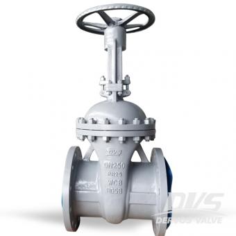
dn250 pn25 게이트 밸브는 din 3352에 따라 설계되었습니다. 볼트로 고정 된 보닛, 외부 요크 및 핸드 휠과 같은 밸브의 공통 부분이있는 몸체는 wcb 및 stl로 만들어집니다. 밸브 본체, 보닛, 시트 및 기타 부품을 추적 할 수 있습니다.
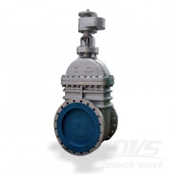
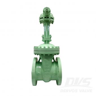
이 게이트 밸브의 부치는 범위가 from 3 인치-32 인치 함께 비 상승 이러한 대형 밸브에서 흔히 볼 수없는 게이트 밸브 및 솔리드 쐐기, these 게이트 밸브는 매우 특별하고 신뢰할 수 있습니다.
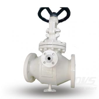
이 DN50 게이트 밸브는 직경 범위가 DN50에서 DN150인 최신 가열 재킷 게이트 밸브의 최신 배치 중 하나입니다.
Dervos는 중국의 자랑스러운 산업용 API 600 주강 게이트 밸브 제조업체입니다. 당사의 스테인리스강 게이트 밸브, 탄소강 게이트 밸브 및 합금강 게이트 밸브는 모든 트림 구성으로 제공됩니다.
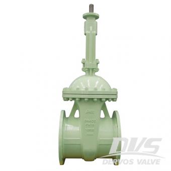
DN400 PN16 게이트 밸브는 EN1984 표준에 따라 만들어졌습니다. 밸브 본체는 1.0619 + STL로 만들어집니다. 그것은 600mm의 구조적 길이와 상승 줄기의 구조적 특성을 가지고 있습니다.
2" 600LB 게이트 밸브는 API 600 표준에 따라 만들어집니다. 밸브 본체는 ASTM A216 WCB로 만들어집니다. 상승 줄기, 브래킷, 풀 보어 및 탄성 쐐기의 구조적 특성을 가지고 있습니다. 연결 모드는 RTJ입니다. 그리고 손이 있습니다. 휠 작동 모드.
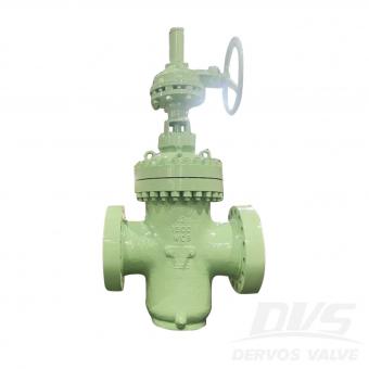
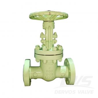
12" 300LB 게이트 밸브는 API600 표준에 따라 제작되었습니다. 밸브 본체는 ASTM A216 WCB로 제작되었습니다. 볼트 커버, 라이징 스템, 탄성 게이트 및 완전 흐름의 구조적 특성을 가지고 있습니다. 연결 모드는 RF입니다. 그리고 기어박스가 있습니다. 작동 모드.
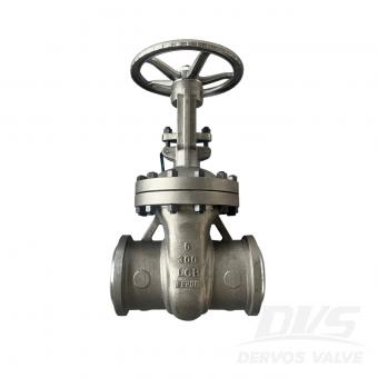
6" 300LB 게이트 밸브는 API 600 표준에 따라 제작됩니다. 밸브 몸체는 A352 LCB로 제작됩니다. 볼트 커버, 라이징 스템, OS&Y의 구조적 특성을 가지고 있습니다. 연결 모드는 BW(SCH40)입니다. 그리고 핸드휠 작동이 가능합니다. 방법.